Threaded Tool Joint Connection

a tool joint and threaded connection technology, applied in the direction of hose connection, screw threaded connection, mechanical apparatus, etc., can solve the problems of reducing torque capability, unable to allow a “slim-hole” design, and the id of the connection cannot be as larg

Active Publication Date: 2014-11-13
TEXAS STEEL CONVERSION INC
View PDF0 Cites 27 Cited by
  • Summary
  • Abstract
  • Description
  • Claims
  • Application Information

AI Technical Summary

Benefits of technology

[0016]The joint connection is characterized by: both the pin external threads and the box internal threads having a thread taper between 0.75 inch per foot and 1.0 inch per foot; both the pin external threads and the box internal threads having a stab flank angle and a load flank angle that are equal, and that are in a range from thirty-three to thirty-nine degrees; both the pin external threads and the box internal threads having roots formed in a shape of a portion of a circle tangent to both thread flanks with a minimum radius of 0.063 inch; the pin external threads being in the range of two to three per inch; the mating box internal threads also being in the range of two to three per inch; the box counterbore having a length of 0.750 or less; and the pin nose having a length in a range of 30% to 90% of the length of the box counterbore.

Problems solved by technology

However, such a taper decreases the amount of cross-sectional area that is at the secondary (internal) shoulder, which reduces torque capabilities.
Also, with such a taper the ID of the connection cannot be as large as shallower taper connections, because there will be a conflict with maintaining enough steel to have an internal shoulder.
Finally, such a taper does not allow a “slim-hole” design, that is, a design having a small OD and a large ID.
In each of these designs, offsetting the root radii undercuts one of the thread flanks, weakening the threads' shear capacity, and are limited to radii less than 0.063.
These parameters are interdependent, so that it is not possible to simply change one at a time without affecting performance.
But, a long box counterbore and long pin nose lengths leads to instability (swelling) of these critical sections as described by Smith (paper “Box OD Stability of Double Shouldered Tool Joints at Catastrophic Failure” presented by J. E. Smith et. al. at the March 1996 SPE / IADC Drilling Conference).

Method used


Image

  • Threaded Tool Joint Connection
  • Threaded Tool Joint Connection
  • Threaded Tool Joint Connection

Examples


Embodiment Construction

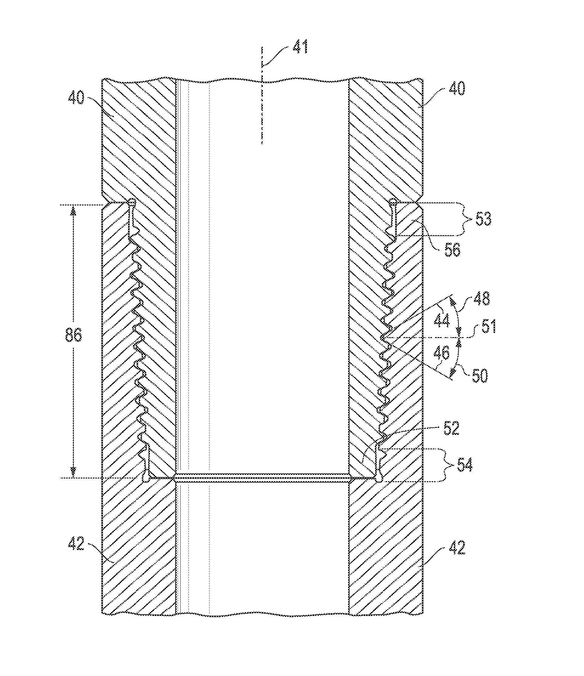
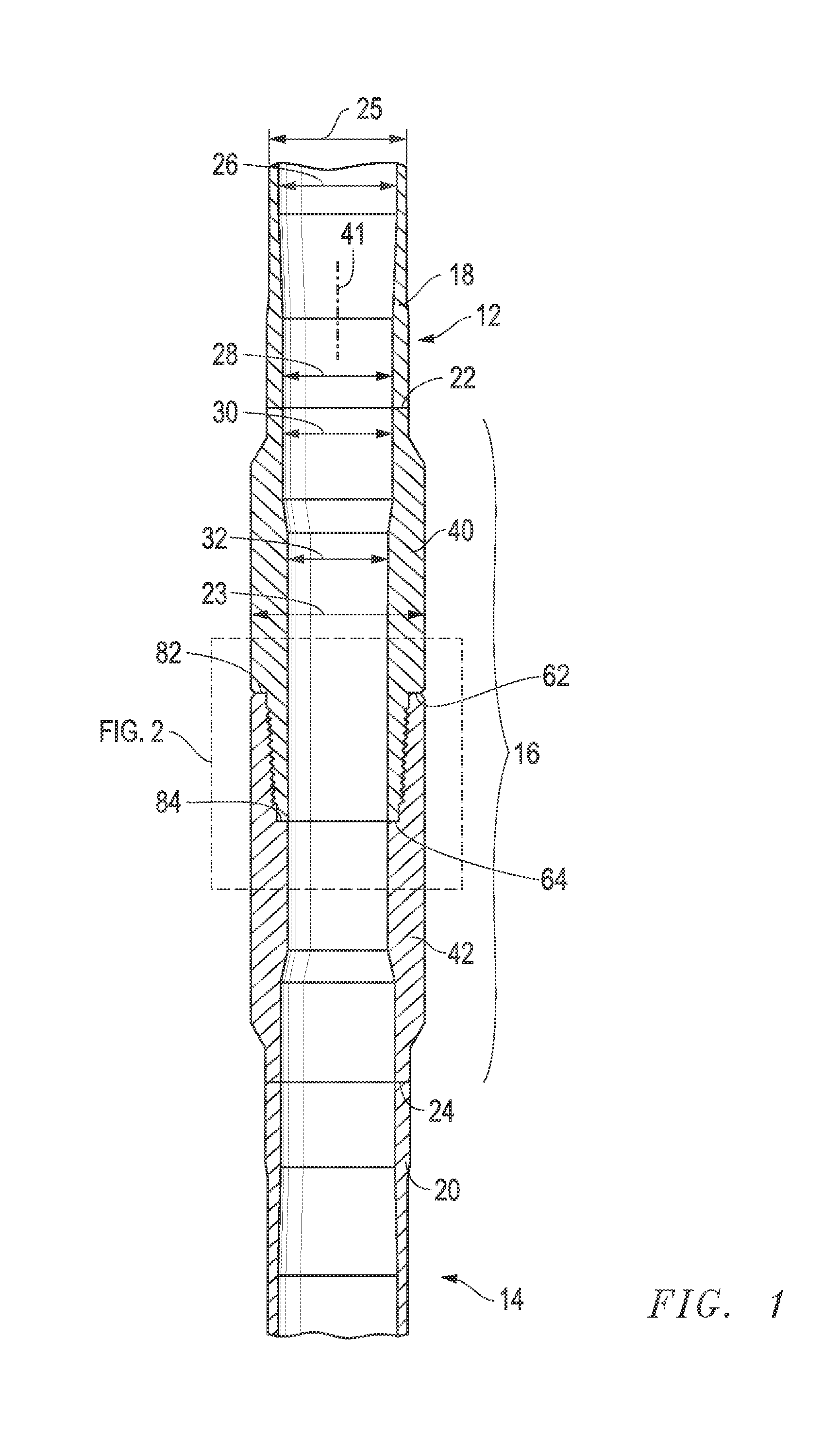
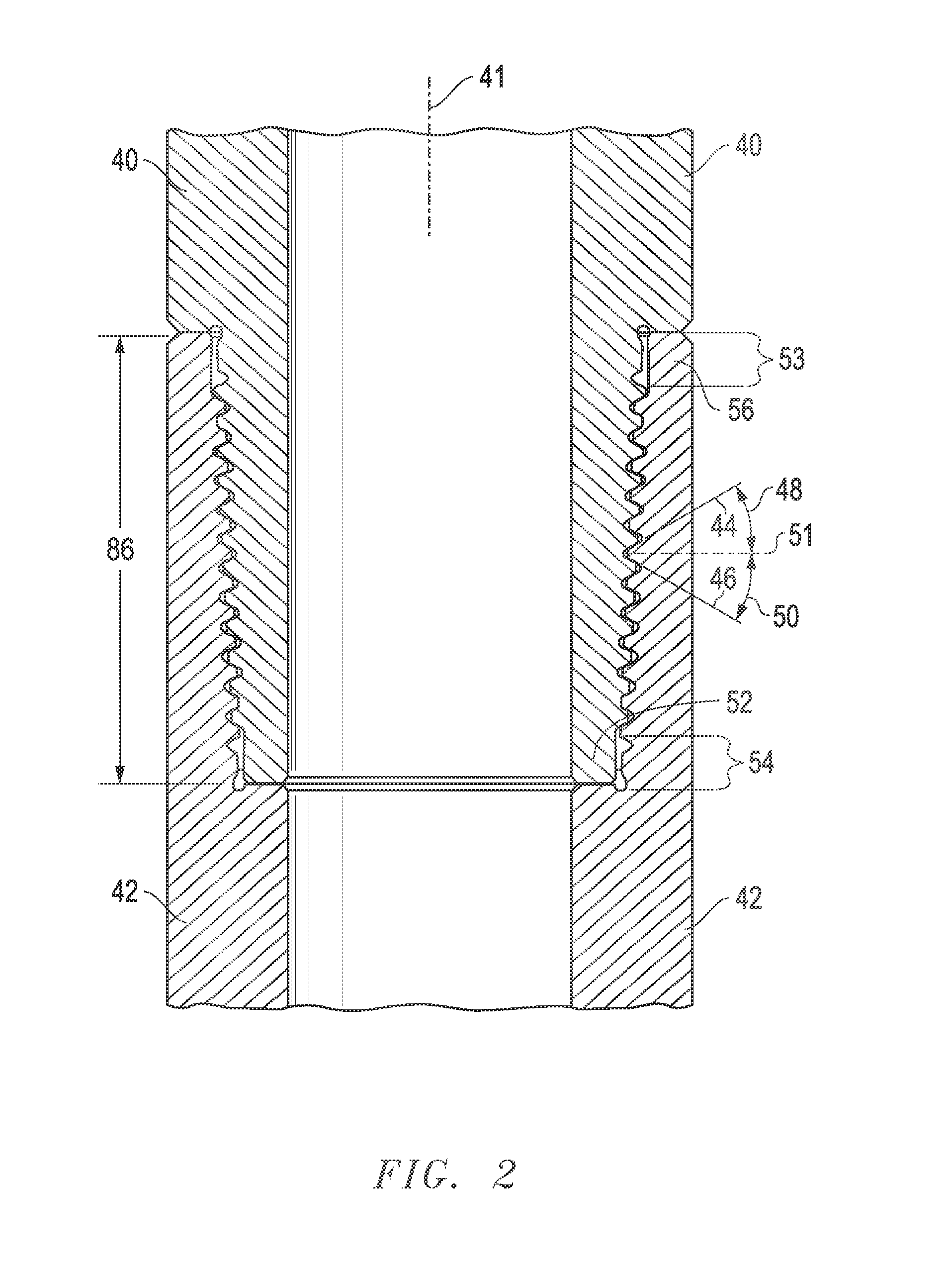
[0023]In FIG. 1, an upper drill pipe 12 connects to a lower drill pipe 14 by means of a tool joint 16 according to the present invention. The drill pipes 12, 14 have upset portions 18, 20 which have thicker wall thickness for welds 22, 24 at the ends of the drill pipes 12, 14 to the ends of the tool joint 16. The tool joint 16 outer diameter 23 is larger than the outer diameter 25 of the drill pipes 12, 14. The inner diameter 26 of the drill pipes 12, 14, is larger than the inner diameter 28 of the upset portions 18, 20. The inner diameter 28 is substantially the same as the inner diameter 30 near the weld ends of the tool joint 16. In this preferred embodiment, the inner diameter 30 of the tool joint is greater than the inner diameter 32 of the section of the tool joint adjacent the threads of the pin 40 and box 42. The pin 40 and the box 42 both taper at seven-eighths of an inch per foot, and have the same centerline 41. Using a taper of less than 1 inch per foot allows the invent...


PUM


Abstract

In a double-shoulder threaded tool joint connection, the pin external threads and the box internal threads have a thread taper between 0.75 inch per foot and 1.0 inch per foot. The pin external threads and the box internal threads have equal stab flank and load flank angles, and are in a range from thirty-three to thirty-nine degrees. Both the pin external threads and the box internal threads have roots formed in a shape of a portion of a circle tangent to both thread flanks with a minimum radius of 0.063 inch. The pin external threads and the box internal threads are in the range of two to three per inch. The box counterbore has a length of 0.750 or less. The pin nose has a length in a range of 30% to 90% of the length of the box counterbore.

Description

CROSS-REFERENCES TO RELATED APPLICATIONS[0001]This is a continuation-in-part of application Ser. No. 12 / 502,722, filed Jul. 14, 2009.STATEMENT REGARDING FEDERALLY SPONSORED RESEARCH OR DEVELOPMENT[0002]None.REFERENCE TO A “SEQUENCE LISTING”, A TABLE, OR A COMPUTER PROGRAM LISTING APPENDIX SUBMITTED ON A COMPACT DISC AND AN INCORPORATION BY REFERENCE OF THE MATERIAL ON THE COMPACT DISC[0003]None.BACKGROUND OF THE INVENTION[0004](1) Field of the Invention[0005]The invention relates in general to drill stern threaded connections used in oil field and trenchless horizontal drilling operations. In particular, the present invention relates to threaded connections on drill pipe tool joints, heavy weight drill pipe, drill collars, and or other drill stern elements. Still more particularly, this invention relates to double shouldered connections capable of withstanding increased torque. bending and tensile loading, while maintaining a tool joint with a large ID and a small. OD.[0006](2) Desc...

Claims


Application Information

Patent Timeline
Patent Type & Authority Applications(United States)
IPC IPC(8): E21B17/042F16L15/06
CPCE21B17/042F16L15/06F16L15/001
Inventor PACHECO, CAIN
Owner TEXAS STEEL CONVERSION INC
Why Eureka
Try Eureka