Method for manufacturing intake manifold and intake manifold
- Summary
- Abstract
- Description
- Claims
- Application Information
AI Technical Summary
Benefits of technology
Problems solved by technology
Method used
Image

Examples
Embodiment Construction
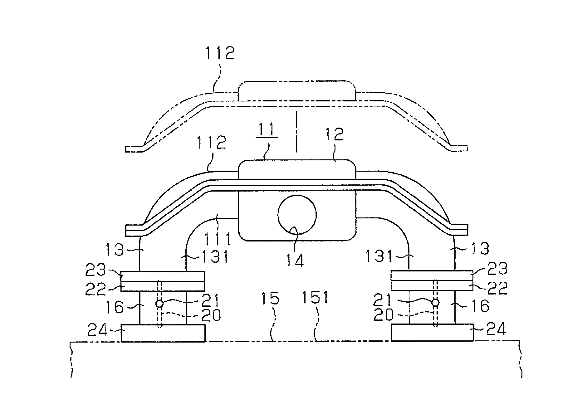
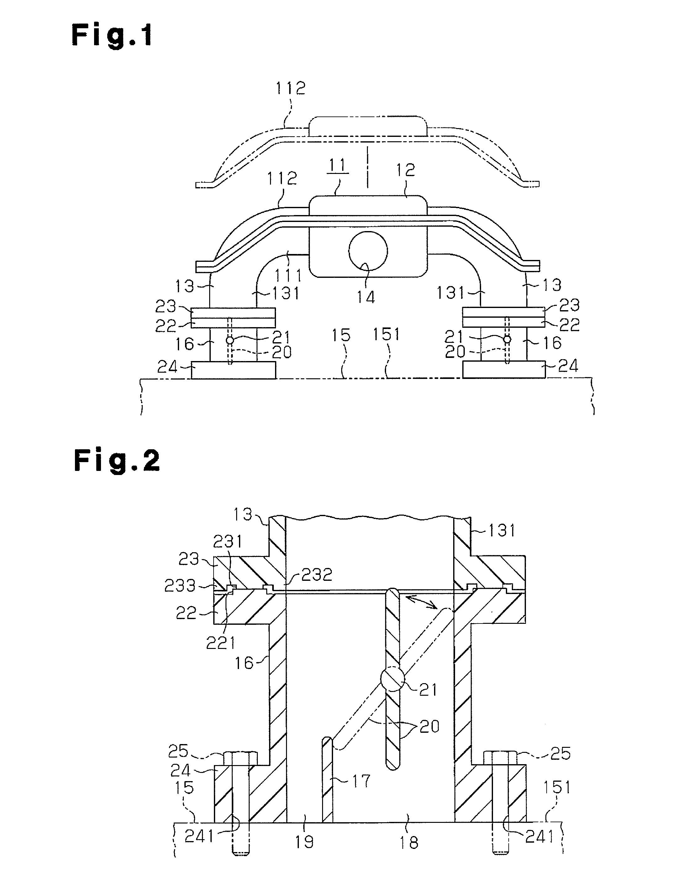
[0016]A method for manufacturing an intake manifold and an intake manifold according to one embodiment will now be described with reference to the drawings. First, the structure of an intake manifold for a horizontally opposed four cylinder engine will be described. The present embodiment will be described. In the description, the right-and-left direction in FIG. 1 is defined as the right-and-left direction of an intake manifold, and the direction perpendicular to the sheet of FIG. 1 is defined as the front-rear direction of the intake manifold.
[0017]An intake manifold 11 illustrated in FIGS. 1 to 3 is entirely made of a heat-resistant plastic such as polyamide plastic.
[0018]As shown in FIG. 1, the intake manifold 11 has a surge tank 12 at the center. The intake manifold 11 also has downwardly curved intake pipes 13 extending from the right and left sides of the surge tank 12 substantially in a bilaterally symmetric manner.
[0019]As shown in FIGS. 1 and 2, the surge tank 12 has in th...
PUM
 Abstract
Description
Claims
Application Information
 - R&D Engineer
- R&D Manager
- IP Professional
- Industry Leading Data Capabilities
- Powerful AI technology
- Patent DNA Extraction
Browse by: Latest US Patents, China's latest patents, Technical Efficacy Thesaurus, Application Domain, Technology Topic.
© 2024 PatSnap. All rights reserved.Legal|Privacy policy|Modern Slavery Act Transparency Statement|Sitemap