
Protective element, protective element fabrication method, and battery module in which protective element is embedded

Active Publication Date: 2014-11-20
DEXERIALS CORP
View PDF8 Cites 22 Cited by
  • Summary
  • Abstract
  • Description
  • Claims
  • Application Information

AI Technical Summary

Benefits of technology

The present invention provides a protective element that can safely and reliably blow out a low-melting point metal using a heating body. The protective element has a reduced height and is embedded in a battery module. The heating body is sandwiched between two insulating members, which allows for highly precise adjustment of its position. The design of the protective element prevents the formation of a convex shape, which ensures an uninterrupted flow of the low-melting point metal when heated and allowed to flow. Overall, the invention allows for a reliable blowout of the low-melting point metal while maintaining a reduced height.

Problems solved by technology

Furthermore, because a comparative large protruding portion is formed on a gap between electrodes to which the low-melting point metal is connected, upon heating the low-melting point metal to be allowed to flow, the flux is interrupted that may cause a longer period of time for a blowout.

Method used


Image

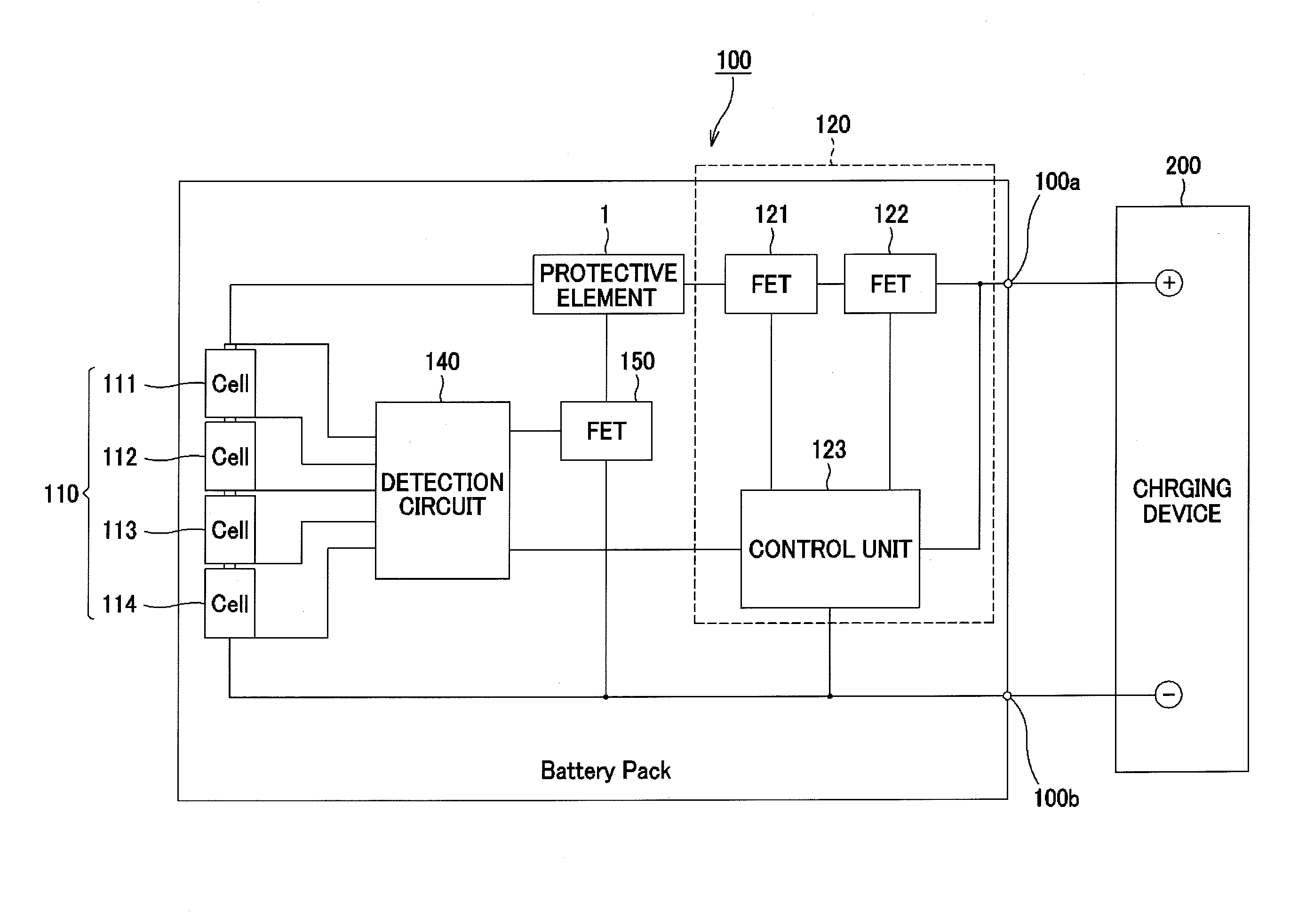
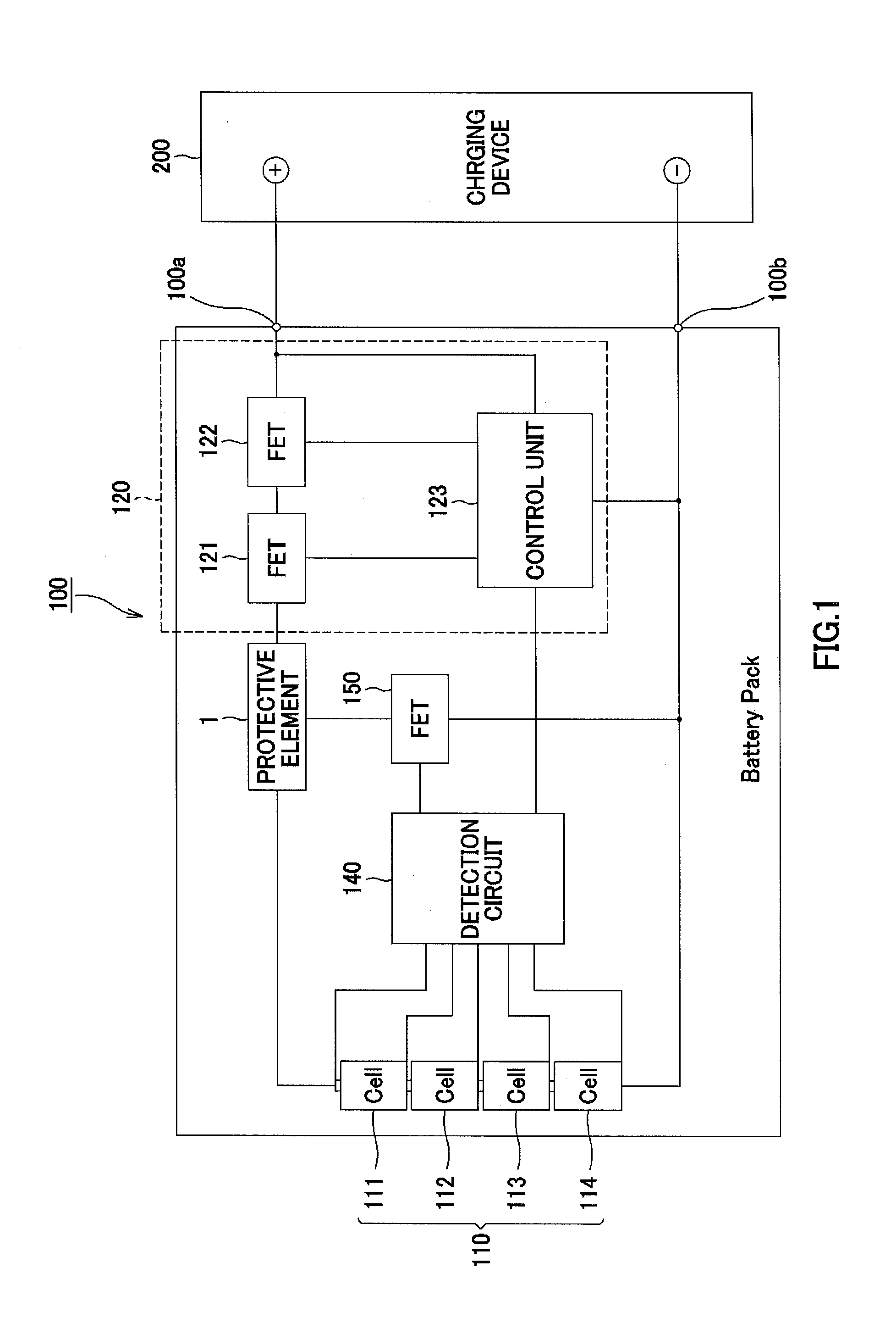
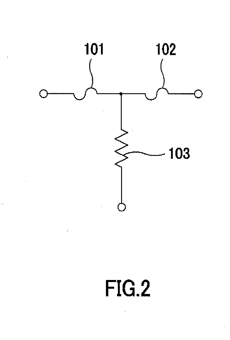
  • Protective element, protective element fabrication method, and battery module in which protective element is embedded
  • Protective element, protective element fabrication method, and battery module in which protective element is embedded
  • Protective element, protective element fabrication method, and battery module in which protective element is embedded

Examples


Embodiment Construction

[0035]In embodiments of the invention, numerous specific details are set forth in order to provide a more thorough understanding of the invention. However, it will be apparent to one with ordinary skill in the art that the invention may be practiced without these specific details. In other instances, well-known features have not been described in detail to avoid obscuring the invention. Referring to Figs., the following description will discuss embodiments for carrying out one or more embodiments of the present invention in detail. Additionally, the present invention is not intended to be limited only by the following embodiments, and various modifications may be made therein without departing from the scope of one or more embodiments of the present invention.

[0036]A protective element according to one or more embodiments of the present invention may include a circuit embedded in a battery composed of chargeable and dischargeable battery cells and a charging and discharging control ...


PUM

PropertyMeasurementUnit
Thicknessaaaaaaaaaa
Electric potential / voltageaaaaaaaaaa
Thermal conductivityaaaaaaaaaa

Abstract

A protective element including a substrate having a first insulating member and a concave portion formed thereon, a heating body layered on the concave portion of the substrate, a second insulating member layered on the substrate so as to cover at least covering the heating body, first and second electrodes layered on a surface of the substrate on which the second insulating member is layered, a heating body electrode layered on the second insulating member so as to be superimposed with the heating body, and electrically connected to a current path between the first and the second electrodes as well as onto and the heating body, and a low-melting point metal layered from the heating body electrode toward the first and the second electrodes configured to cause a blowout of the current path between the first and the second electrodes by heating.

Description

CROSS-REFERENCE TO RELATED APPLICATIONS[0001]This application is a National Stage application of International Patent Application No. PCT / JP2012 / 082684, filed on Dec. 17, 2012, and claims priority pursuant to 35 U.S.C. §119(a) to Japanese Patent Application No. P2011-277123, filed on Dec. 19, 2011, and Japanese Patent Application No. P2012-274222, filed on Dec. 17, 2012. The international application and priority applications are hereby incorporated by reference in their entirety.BACKGROUND OF INVENTION[0002]1. Field of the Invention[0003]One or more embodiments of the present invention relate to a protective element that protects a circuit connected onto a current path by causing a blowout to the current path, a method for manufacturing such a protective element, and a battery module in which the protective element is embedded.[0004]2. Background Art[0005]In general, a charging and discharging circuit for a secondary battery, such as a lithium ion battery or the like, has a functio...

Claims


Application Information

Patent Timeline
IPC IPC(8): H02J7/00H01H69/02H01H85/02H01M50/583
CPCH02J7/0029H02J7/007H02J2007/004H01H69/022H02J2007/0037H01H85/0241H01M10/0525H02H3/08H01M2200/103H02J7/0031H02H7/18H02H9/041H02H9/042Y10T29/49208H02J7/00302H02J7/00306Y02E60/10H01H37/761H01H2085/466H01H61/02H01M50/583H01H37/76H01M10/44H01M50/572H01M10/48G08B21/00G01N27/416
Inventor KOMORI, CHISATOFURUUCHI, YUJIYONEDA, YOSHIHIROMUKAI, KOICHIEJIMA, KOJIFUJIHATA, TAKASHIFURUTA, KAZUTAKAARAKI, TOSHIAKI
Owner DEXERIALS CORP
Learn More