Apparatus, system, and method of inspecting image, and recording medium storing image inspection control program

Inactive Publication Date: 2014-11-20
RICOH KK
View PDF11 Cites 17 Cited by
  • Summary
  • Abstract
  • Description
  • Claims
  • Application Information

AI Technical Summary

Benefits of technology

This is a device used to inspect images that are printed or displayed on a screen. It works by getting data from the image and comparing it to a reference image to find any defects. The device then looks for any alignment issues between the read image and the reference image. This makes it easier to determine if the image was printed correctly and if any errors were made during the process.

Problems solved by technology

In such case, comparing the printed matter with the master image generated from the previously printed matter would be inefficient.
However, a reference point suitable for position alignment cannot always be extracted from an image.
Therefore, when a reference point suitable for position alignment cannot be extracted, the rotational correction process may become inadequate for aligning the read image and the master image.
If a shift has arisen such that position alignment is inadequate in the comparison area of both images, it may be determined that there is a defect despite normal printed matter if during inspection it is determined that the degree of the difference is high.
However, such a process may increase the computation time and when the processing time for an inspection has restrictions, such as the processing capacity of an inspection apparatus, the inspection process may end in the middle of a calculation due to the restrictions on processing time.
In such an instance, the inspection process may not be completed and the correct result may not be obtained and it may be erroneously determined that the printed matter has a defect.
Accordingly, during the inspection of the printed matter by an inspection apparatus, even though there is no defect in the printed matter it may be determined that a defect exists in the printed matter based on a defect in the position alignment thereby providing an incorrect inspection result.
Therefore, the user will then need to confirm whether the printed matter judged to be defective is truly defective thereby creating a large burden for the user.
Moreover, even if it is a case where the technique of JP No. 2006-007659-A is employed such that the resolution of the defective part of the printed matter is made high and is prominently displayed, it still cannot be determined whether the printed matter truly contains a defect without confirmation from a user.

Method used


Image

  • Apparatus, system, and method of inspecting image, and recording medium storing image inspection control program
  • Apparatus, system, and method of inspecting image, and recording medium storing image inspection control program
  • Apparatus, system, and method of inspecting image, and recording medium storing image inspection control program

Examples


Embodiment Construction

[0033]The terminology used herein is for the purpose of describing particular embodiments only and is not intended to be limiting of the present invention. As used herein, the singular forms “a”, “an” and “the” are intended to include the plural forms as well, unless the context clearly indicates otherwise. It will be further understood that the terms “includes” and / or “including”, when used in this specification, specify the presence of stated features, integers, steps, operations, elements, and / or components, but do not preclude the presence or addition of one or more other features, integers, steps, operations, elements, components, and / or groups thereof.

[0034]In describing exemplary embodiments shown in the drawings, specific terminology is employed for the sake of clarity. However, the present disclosure is not intended to be limited to the specific terminology so selected and it is to be understood that each specific element includes all technical equivalents that operate in a...


PUM


Abstract

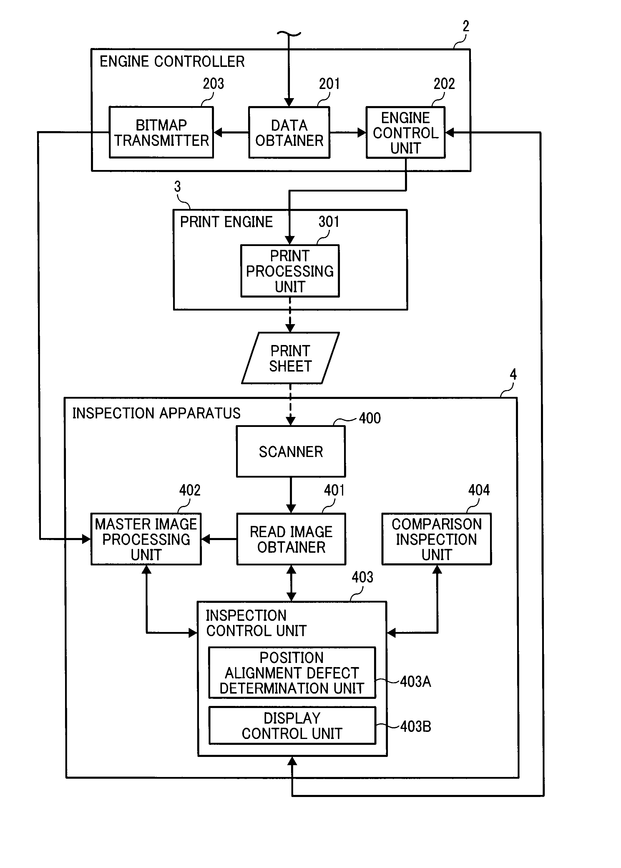
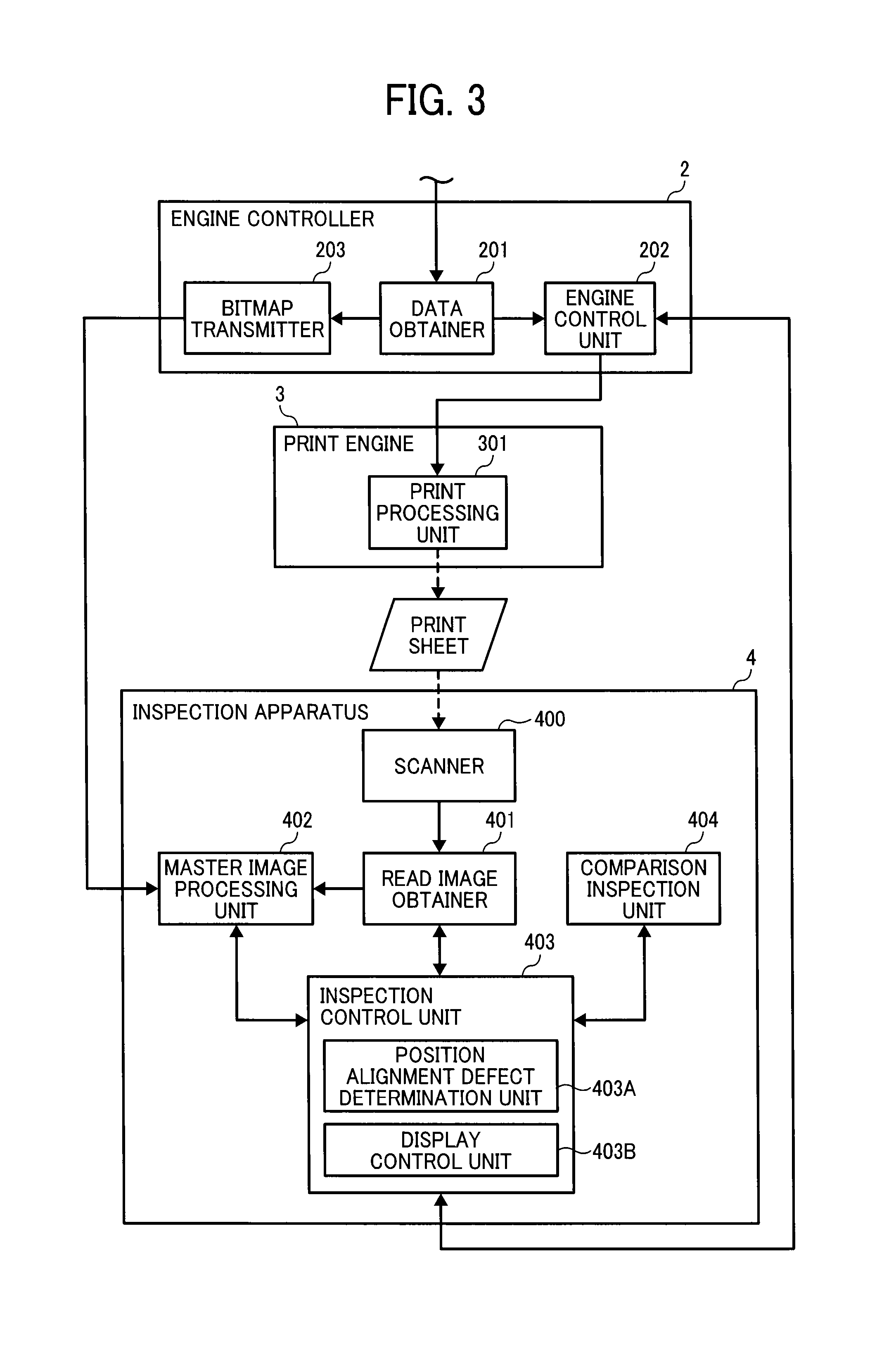
An image inspection apparatus for inspecting an image output on a recording medium. The image inspection apparatus includes processing circuitry that obtains data of an output-target image used by an image forming apparatus to conduct an image forming operation, generates read data from the data of the output-target image, and generates an inspection reference image from the data of the output-target image. The apparatus also performs position alignment between the read image and the inspection reference image, conducts an inspection which determines a defect in the read image based on the difference of the aligned read image and the inspection reference image, and determines whether a position alignment defect exists in the read image based on the defect detected during inspection.

Description

CROSS-REFERENCE TO RELATED APPLICATIONS[0001]This patent application is based on and claims priority pursuant to 35 U.S.C. §119 to Japanese Patent Application No. JP 2013-053994, filed on May 15, 2013 and No. JP 2013-267496, filed on Dec. 25, 2013, in the Japan Patent Office, the entire disclosure of which is hereby incorporated by reference.BACKGROUND[0002]1. Field of the Invention[0003]The present invention relates to an apparatus, system, and method of inspecting an image formed by an image forming apparatus, and a recording medium storing an image inspection control program.[0004]2. Description of the Related Art[0005]Conventionally, the inspection of printed matter has been performed by human operators. In recent years, inspection apparatuses that automatically inspect printed matter have been widely used, mainly in the field of offset printing. For example, in conventional devices, a master image is generated by reading specific printed matter that is selected based on the ima...

Claims


Application Information

Patent Timeline
IPC IPC(8): G06T7/00
CPCG06T7/001G06T2207/10008G06T7/0008G06T2207/30176G06T2207/30144
Inventor ARAKI, ATOKITAI, TADASHI
Owner RICOH KK
Why Eureka
Try Eureka