
Eureka
For R&D, Eureka makes reading and utilizing patents & technical documents easy.
Eureka AIR
Designed for self-driven R&D workflows. Generate viable solutions, solve complex R&D challenges, empower your innovation with AI.

Eureka Materials
Designed for material experts only. Revolutionize your material R&D, from search, analyze, to developing new materials.

TechResearch
Generate reliable direction feasibility study reports for your R&D in just a few steps.

TechSeek
Discover and master advanced knowledge NOW. Basics, ideas, possibilities, all at once.

TechMind
As an expert in R&D Theories, TechMind can generates customized viable solutions instantly.

TechRisk
Analyze your overall solution with one click, know your potential R&D risks in advance.

TechMonitor
Get weekly tech updates, stay abreast of the latest tech innovations and key insights.
Fluid path structure and method of manufacturing the same
- Summary
- Abstract
- Description
- Claims
- Application Information
AI Technical Summary
Benefits of technology
Problems solved by technology
Method used
Image


Examples
first embodiment
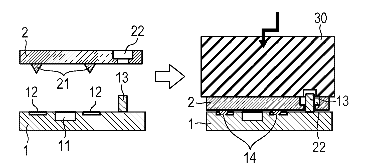
[0022]FIGS. 1A and 1B are schematic cross-sectional views of an embodiment of fluid path structure. The fluid path structure of this embodiment is formed by joining a first member to be welded (to be referred to as first weld member hereinafter) 1 and a second member to be welded (to be referred to as second weld member hereinafter) 2 together by means of ultrasonic welding. FIG. 1A is a cross-sectional view, representing the two weld members 1 and 2 before they are actually welded. As illustrated in FIG. 1A, a fluid path groove (ink path) 11 that is U-shaped in cross section and a plurality of welding grooves 12 that are arranged outside the fluid path groove 11 are formed in the first weld member from the surface (joint surface) thereof that is to be joined with the second weld member 2. Additionally, a projection 13 is also formed on the same surface of the first weld member 1 as integral part thereof.
[0023]On the other hand, a plurality of ribs 21 are arranged on the surface (jo...
second embodiment
[0048]Now, the second embodiment of the present invention will be described below.
[0049]FIG. 7 illustrates the basic configuration of inkjet head 1000 that is a liquid ejection head including a fluid path structure according to the present invention. The inkjet head 1000 includes a recording element unit 1002 that includes a recording element board 1100 and an electric wiring board 1300 and a holder unit 1003.
[0050]The recording element board 1100 is formed by using a silicon board having openings that operate as ink supply ports and a plurality of heat-generating resisters are arranged on the board in order to apply thermal energy to ink as thermal energy is required to eject liquid. Such a board on which heat-generating resisters are formed is referred to as heater board. A heater board is provided with wiring for supplying electric power to the heat-generating resisters and electrically connected to the electrode pads arranged at the opposite ends of the board by means of the wir...
PUM
| Property | Measurement | Unit |
|---|---|---|
| Structure | aaaaa | aaaaa |
| Height | aaaaa | aaaaa |
Abstract
Description
Claims
Application Information
 - R&D Engineer
- R&D Manager
- IP Professional
- Industry Leading Data Capabilities
- Powerful AI technology
- Patent DNA Extraction
Browse by: Latest US Patents, China's latest patents, Technical Efficacy Thesaurus, Application Domain, Technology Topic, Popular Technical Reports.
© 2024 PatSnap. All rights reserved.Legal|Privacy policy|Modern Slavery Act Transparency Statement|Sitemap|About US| Contact US: help@patsnap.com