Communication device, radio communication system, radio communication method, and terminal

a communication device and radio communication technology, applied in the field of communication devices, radio communication systems, radio communication methods, and terminals, can solve the problems of disadvantageous failure of providing stable communications, reducing the battery lift of the terminal, and conventional techniques failing to provide a mechanism for assuring power, etc., to ensure the stability of reception power, and ensure the effect of stable communication using the second radio communication schem

Inactive Publication Date: 2014-12-18
HITACHI LTD
View PDF14 Cites 0 Cited by
  • Summary
  • Abstract
  • Description
  • Claims
  • Application Information

AI Technical Summary

Benefits of technology

[0020]The reception power in the communication using the second radio communication scheme is estimated on the basis of the reception power measured during communications using the first radio communication scheme. The first radio communication scheme is therefore switched to the second radio communication scheme under the condition that the sufficiency and stability of the reception power are assured. In this way, stable communication using the second radio communication scheme can be assured. If the second radio communication scheme is implemented using a wireless LAN, the switching can be done while the reception power is stable. Consequently, it is possible to provide merits of eliminating the need to regularly perform a search process, thereby giving a long battery life to a terminal and avoiding unstable communications that would be caused, for example, when a connection to a wireless LAN is made at a place with low reception power.

Problems solved by technology

A disadvantage of radio communication systems that switch between two radio communication schemes is that the battery lift of a terminal decreases, because the terminal needs to search for a base station for the second radio communication scheme while conducting communications using the first radio communication scheme.
When a server device reports a connection policy that switches from the first communication radio scheme to the second radio communication scheme, however, conventional techniques fail to provide a mechanism for assuring the power stability of a radio wave that a terminal will receive by using a second radio communication scheme.
Therefore, if the reception power of the terminal for the second radio scheme is low when the switch to the second radio communication scheme is done, it takes a long time to authorize the terminal, so that providing stable communications is disadvantageously failed.
Thus, this technique is not designed to provide stable connections between different radio communication schemes.

Method used


Image

  • Communication device, radio communication system, radio communication method, and terminal
  • Communication device, radio communication system, radio communication method, and terminal
  • Communication device, radio communication system, radio communication method, and terminal

Examples


example 1

[0052]An embodiment of the present invention will be described below with reference to the drawings.

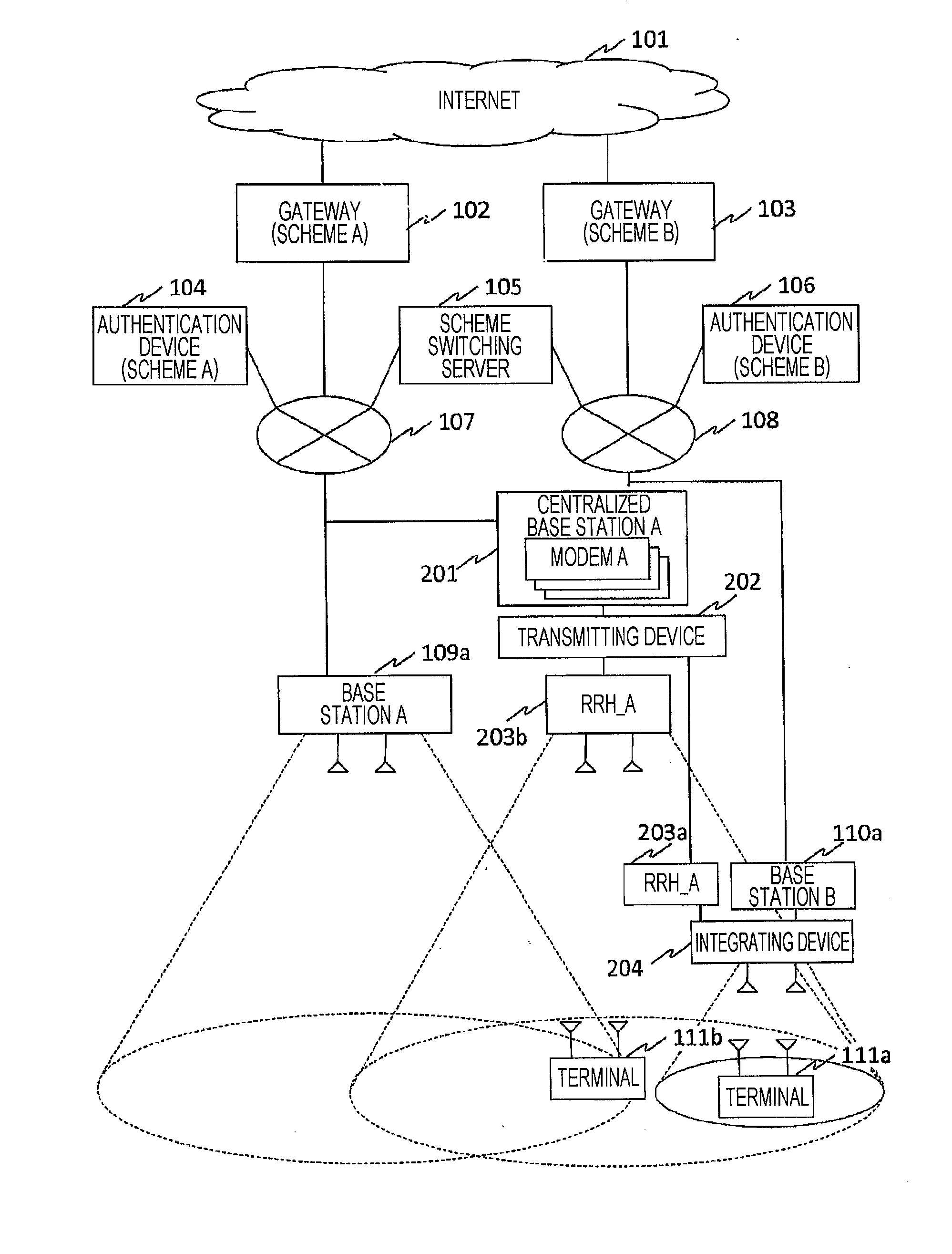
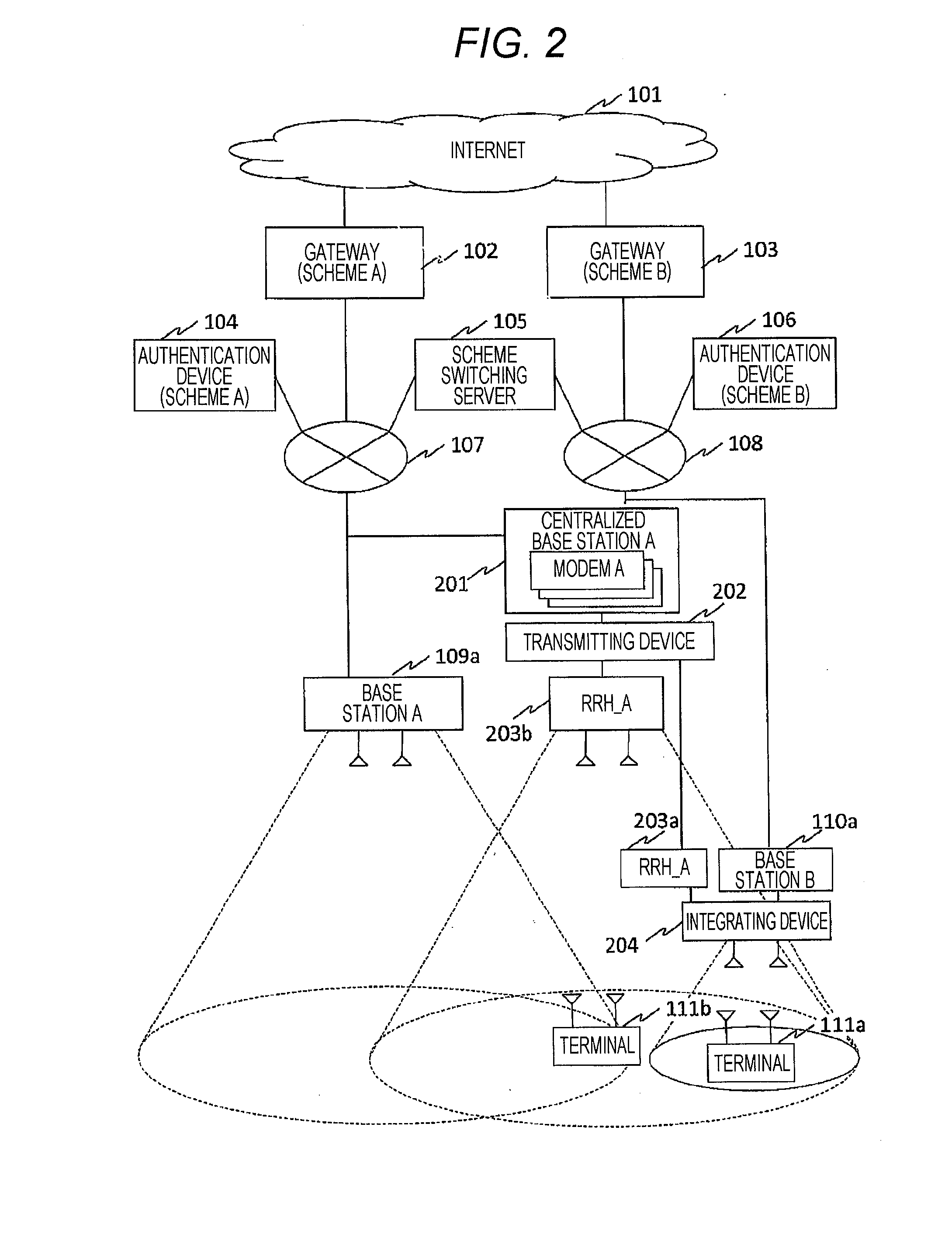
[0053]FIG. 2 shows a system configuration in Embodiment 1 of the present invention.

[0054]An Internet 101, a gateway (scheme A) 102, a gateway (scheme B) 103, an authentication device (scheme A) 104, an authentication device (scheme B) 106, a scheme switching server 105, a base station A 109a, a base station B 110a, a terminal 111a, and a terminal 111b have substantially the same system configurations as in those shown in FIG. 1. An integrating device 204 is installed in a transmission / reception antenna of the base station B 110a, so that this antenna handles both signals for the schemes A and B. A radio device RRH_A 203a, which transmits or receives signals for the scheme A, exchanges the signals for the scheme A with the integrating device 204. In addition, a radio device RRH_A 203b that transmits or receives signals for the scheme A is installed in the place where the base station A...

example 2

[0099]FIG. 7 is an explanatory, operational sequence diagram (Example 2) in Embodiment 1 of the present invention, in which the scheme B is switched to the scheme A.

[0100]A control message for a scheme A check request in FIG. 7 contains the same information elements as in the control message for the scheme B check request in FIG. 4, but the types of their control messages differ from each other.

[0101]Likewise, information elements are identical but message types are different between respective control messages for the scheme A check request response and the scheme B check request response, for the scheme A check instruction and the scheme B check instruction, and for the scheme A check instruction response and the scheme B check instruction response.

[0102]The terminal 111a receives reference signals B that the base station 110a regularly transmits, and measures the reception power of a reference signal B. The terminal 111a reports the measurement result for the reception power to t...


PUM


Abstract

Reception power of a terminal for a first communication scheme is measured. A propagation path loss between a base station and the terminal is calculated. The propagation path loss is estimated in a case where communications are conducted using a second communication scheme, and reception power of the terminal is estimated from output of the base station for the second communication scheme and the estimated propagation path loss. If the sufficiency and stability of the reception power are assumed, the switching from the first communication scheme to the second communication scheme is done. In this way, stable communications using the second communication scheme are ensured.

Description

CROSS-REFERENCE TO RELATED APPLICATION[0001]This application claims the priority of Japanese Patent Application No. 2013-127093 filed Jul. 18, 2013, which is incorporated herein by reference in its entity.BACKGROUND OF THE INVENTION[0002]1. Field of the Invention[0003]The present invention relates to a communication method of enabling a radio communication system that handles a plurality of radio communication schemes or frequencies to switch to a suitable one.[0004]2. Description of the Related Art[0005]In radio communication systems represented by portable phones, high-speed data communications have been increasingly demanded, for example, due to the advent of smartphones. Mobile traffic is accordingly increasing rapidly.[0006]Approaches of accommodating such rapidly increasing mobile traffic include: a method of increasing the number of usable bands for frequency resources; a method of improving frequency usage efficiency, which increases the amount of information to be transmitt...

Claims


Application Information

Patent Timeline
Patent Type & Authority Applications(United States)
IPC IPC(8): H04W52/02
CPCH04W52/0229H04W52/16H04W52/242H04W52/245H04W52/38Y02D30/70
Inventor TAMAKI, TSUYOSHIISHII, HIROTAKE
Owner HITACHI LTD
Why Eureka
Try Eureka