Pneumatic tire security system employing internal high pressure air bag

a technology of pneumatic tires and air bags, applied in the field of pneumatic tires, can solve the problems of tire repair, inconvenient and dangerous, vehicle cannot continue,

Active Publication Date: 2015-01-15
MORTY KAPLAN 2010 IRREVOCABLE TRUST
View PDF5 Cites 11 Cited by
  • Summary
  • Abstract
  • Description
  • Claims
  • Application Information

AI Technical Summary

Benefits of technology

[0007]The present invention is therefore directed toward a tire security system designed to be supported within a new or in-service conventional pneumatic tire so that it deploys when the outer tire is ruptured to expand and support the damaged tire to allow at least limited driving without the inconveniences of previous run-flat tire systems.
[0014]In one embodiment of the invention, multiple air bags which are spaced radially about the rim, may be employed. This is particularly advantageous for vehicles operating in high-risk environments where multiple air bags may be used for greater protection. For example, if a bullet pierces the tire and one air bag, the other air bags may expand to fill the tire volume.

Problems solved by technology

When conventional pneumatic tires of the type used on automobiles, trucks, and the like are damaged, by a puncture or the like, so that they lose pressure and collapse, the vehicle is unable to continue and the tire must be repaired or replaced before driving can continue.
This is both inconvenient and dangerous as tire failures often result in the loss of vehicle control, serious injuries, and fatalities.
A tire failure in busy traffic or a hostile environment can also be dangerous.
In some situations, such as for security vehicles and military applications, it may be very dangerous.
To incorporate the run-flat support, several key performance features are compromised.
These include poor ride, poor handling, poor traction, lower fuel economy, lower life, higher cost, and difficulty of servicing of previous run-flat tires.
Underinflated tires are a major cause of tire failure.
While tire pressure monitoring systems have been adopted for mainstream use on certain vehicles, the automatic tire inflation systems have not been adopted for mainstream use as they are complicated, expensive, and difficult to service.

Method used


Image

  • Pneumatic tire security system employing internal high pressure air bag
  • Pneumatic tire security system employing internal high pressure air bag
  • Pneumatic tire security system employing internal high pressure air bag

Examples


Embodiment Construction

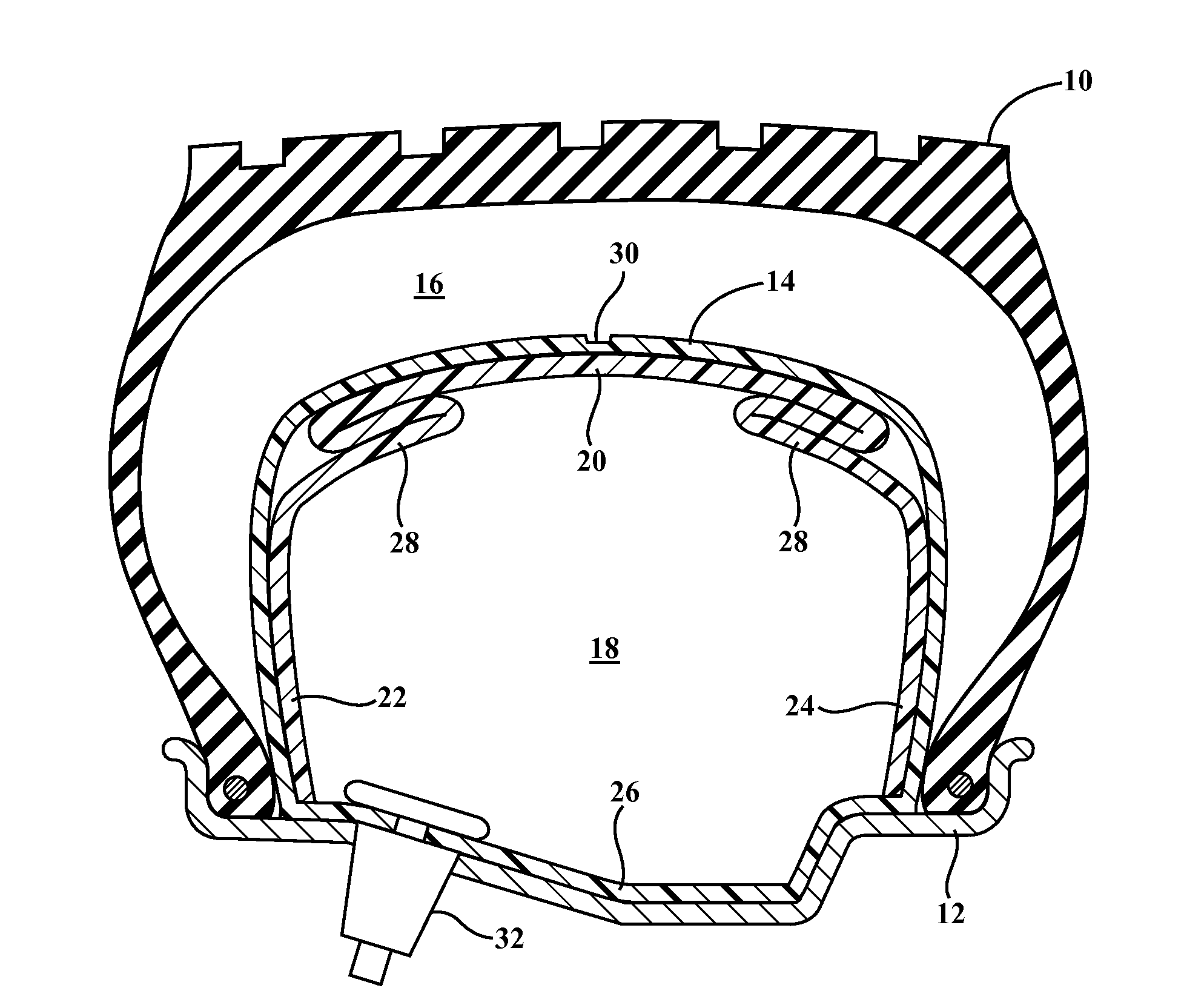
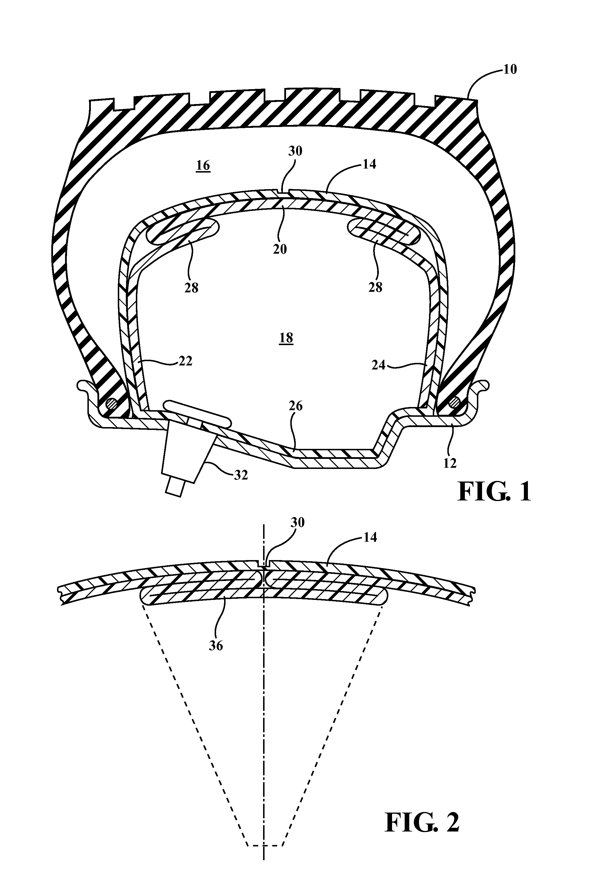
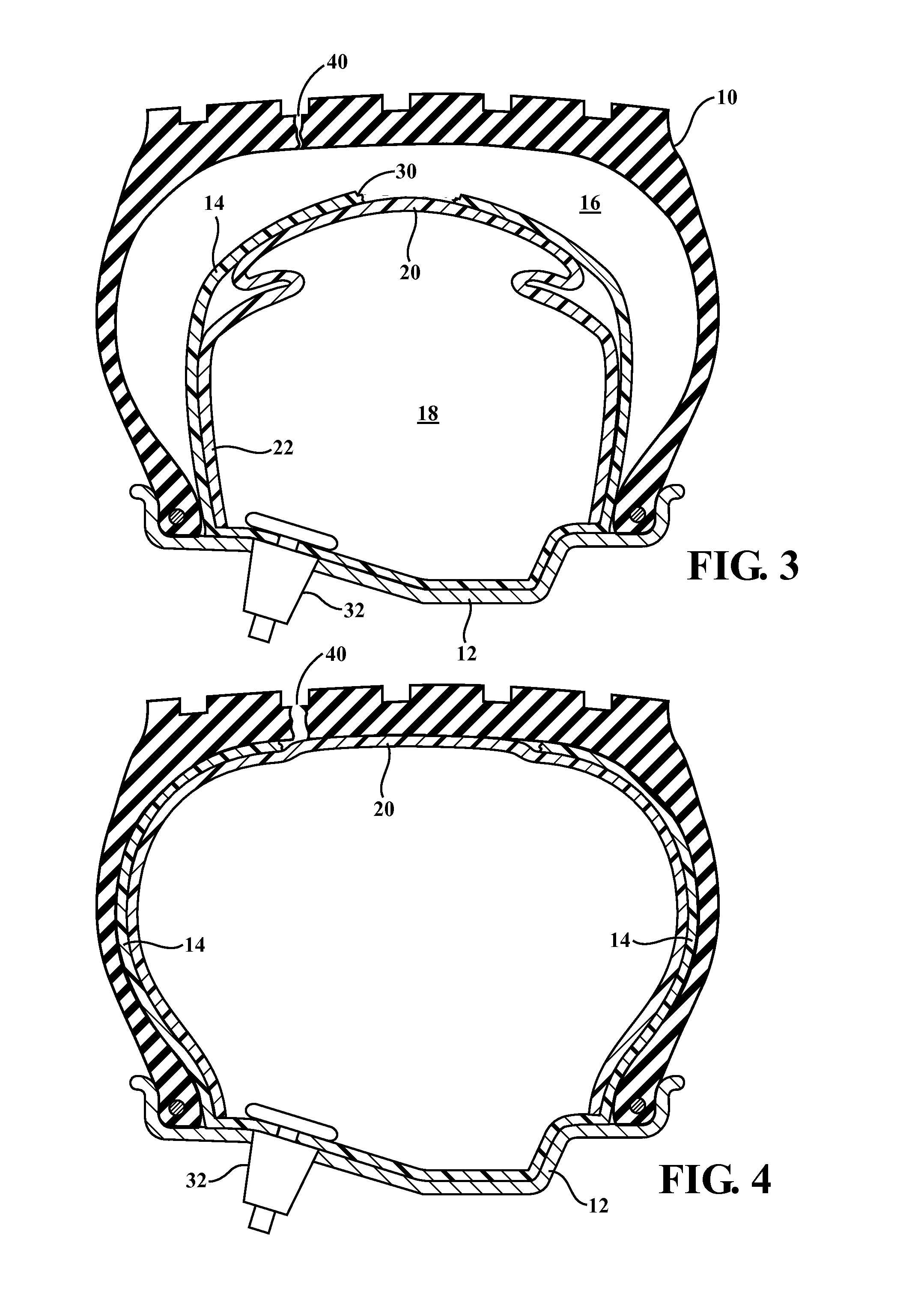
[0025]FIG. 1 is a cross-sectional view through a conventional tire 10 mounted on a conventional wheel rim 12. FIG. 1 does not disclose the inflation valve for the tire volume which would be located at a different rotational position of the rim.

[0026]An air bag container 14, which extends through the entire circumference of the tire 10, divides the volume between the tire and the rim 12 into an outer chamber 16, within the tire 10, and an inner chamber 18, bounded by the rim 12 and the container 14. The chamber 16 may typically contain about 40% of the entire volume between the tire and the rim while the area under the container and air bag 18 would constitute 60% of the volume. These volumes are not critical and may be adjusted in accordance with a preferred design.

[0027]The container encloses an air bag 20 which is formed of a strong flexible material which may be nylon in certain applications, Kevlar® in others, or similar materials. In the preferred embodiment the air bag 20 is i...


PUM


Abstract

A system for allowing a pneumatic tire supported on a wheel rim of a vehicle to continue in operation after rupture of the tire. The system includes an air bag container which divides the interior tire volume into a radial outer chamber providing normal pressure for inflation of the tire and a radial interior chamber, within the air bag, which is inflated to a substantially higher pressure. The container is intended to rupture when the tire is deflated by a puncture or the like allowing the higher pressure air bag to escape from its container and fill the entire tire volume at a normal operating pressure.

Description

CROSS-REFERENCE TO RELATED APPLICATIONS[0001]This application claims priority of U.S. Provisional Patent Application No. 61 / 844,111 filed Jul. 9, 2013, and U.S. Provisional Patent Application No. 61 / 857,444 filed Jul. 23, 2013, the contents of which are incorporated herein by reference.FIELD OF THE INVENTION[0002]This invention relates to pneumatic tires for automotive vehicles and more particularly to a system employing an inflated air bag within the internal volume of a tire that, in the event of a rupture of the tire during service, will expand to allow for continued control and limited operation of the vehicle.BACKGROUND OF THE INVENTION[0003]When conventional pneumatic tires of the type used on automobiles, trucks, and the like are damaged, by a puncture or the like, so that they lose pressure and collapse, the vehicle is unable to continue and the tire must be repaired or replaced before driving can continue. This is both inconvenient and dangerous as tire failures often resul...

Claims


Application Information

Patent Timeline
Patent Type & Authority Applications(United States)
IPC IPC(8): B60C17/02
CPCB60C17/02B60C5/24
Inventor KYLE, RONALD L.
Owner MORTY KAPLAN 2010 IRREVOCABLE TRUST
Why Eureka
Try Eureka