Triangulation scanner having motorized elements

a technology of triangulation scanner and motorized element, which is applied in the field of triangulation scanner, can solve the problems of not being able or efficient to suspend measurement and manually change lenses, and achieve the effect of enhancing capabilities

Inactive Publication Date: 2015-01-15
FARO TECH INC
View PDF5 Cites 81 Cited by
  • Summary
  • Abstract
  • Description
  • Claims
  • Application Information

AI Technical Summary

Problems solved by technology

In an automated system, it may not be possible or efficient to suspend measurement to change lenses manually.

Method used


Image

  • Triangulation scanner having motorized elements
  • Triangulation scanner having motorized elements
  • Triangulation scanner having motorized elements

Examples


example structured

Discussion of Example Structured Light Scanners

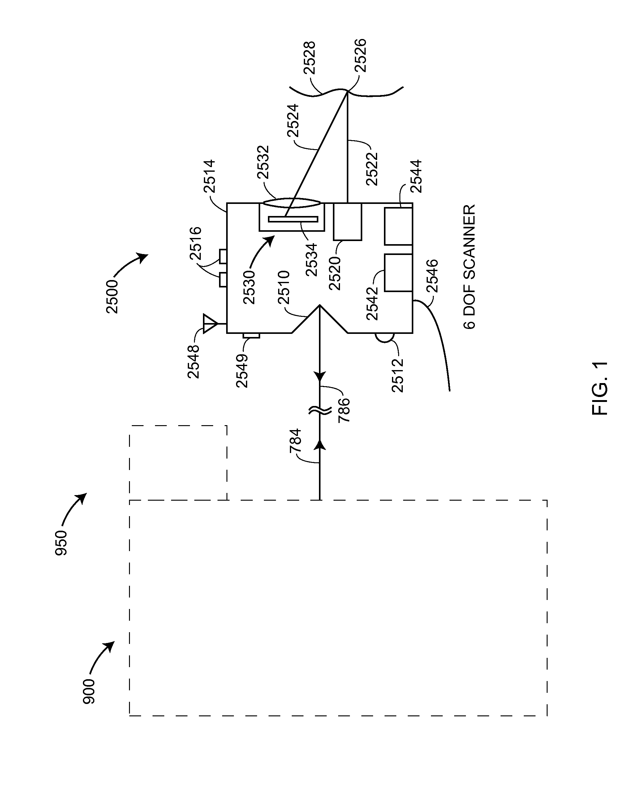
[0025]FIG. 1 shows an embodiment of a six-DOF scanner 2500 used in conjunction with an optoelectronic system 900 and a locator camera system 950. The six-DOF scanner 2500 may also be referred to as a “target scanner.” In another embodiment, the optoelectronic system 900 is replaced by the optoelectronic system that uses two or more wavelengths of light. The six-DOF scanner 2500 includes a body 2514, one or more retroreflectors 2510, 2511 a scanner camera 2530, a scanner light projector 2520, an optional electrical cable 2546, an optional battery 2444, an interface component 2512, an identifier element 2549, actuator buttons 2516, an antenna 2548, and an electronics circuit board 2542. Together, the scanner projector 2520 and the scanner camera 2530 are used to measure the three dimensional coordinates of a workpiece 2528. The camera 2530 includes a camera lens system 2532 and a photosensitive array 2534. The photosensitive array 2534 ma...


PUM


Abstract

A 3D triangulation scanner includes a projector, a camera, and a processor. At least one of the projector and the camera has a zoom lens and a motorized zoom adjustment mechanism. The processor is responsive to executable instructions that uses triangulation calculations to calculate 3D coordinates of points on a surface that are based at least in part on a baseline length, an orientation of the projector and the camera, a position of a corresponding source point on an illuminated pattern source of the projector, and a position of a corresponding image point on a photosensitive array of the camera. The 3D coordinates of the points are calculated at one time and at another time, at least one of the projector FOV being wider at the one time than at the another time or the camera FOV being wider at the one time than at the another time.

Description

CROSS REFERENCE TO RELATED APPLICATIONS[0001]This application claims the benefit of U.S. Provisional Application Ser. No. 61 / 844,627, filed Jul. 10, 2013, which is incorporated herein by reference in its entirety.BACKGROUND[0002]The present disclosure relates to a triangulation scanner that measures three-dimensional (3D) coordinates.[0003]A triangulation scanner measures 3D coordinates of a surface of an object by projecting a pattern of light onto the surface, imaging the light pattern with a camera, and performing a triangulation calculation to determine the 3D coordinates of points on the surface. A triangulation scanner includes a projector and a camera. The projector includes a source that provides an illuminated pattern and a projector lens, and the camera includes a lens and a photosensitive array.[0004]Previously, triangulation scanners have included lenses with fixed focal lengths. To change the focal length of the projector lens or the camera lens, an operator would manua...

Claims


Application Information

Patent Timeline
Patent Type & Authority Applications(United States)
IPC IPC(8): G01B11/00G01B11/14H04N5/225
CPCG01B11/14H04N5/2259G01B11/002G01B11/2513G01B11/2545H04N23/58
Inventor YU, HAO
Owner FARO TECH INC
Why Eureka
Try Eureka