Method and system for finding

a technology of locator and directional antenna, applied in the direction of electric signalling details, using reradiation, instruments, etc., can solve the problems of reducing the directional capability of directional antennas, preventing coordinated searches, and relatively high frequency bands that are not suitable for searching, so as to simplify virtual triangulation and minimize user-device interaction

Active Publication Date: 2006-01-19
QUALCOMM TECHNOLOGIES INC
View PDF1 Cites 158 Cited by
  • Summary
  • Abstract
  • Description
  • Claims
  • Application Information

AI Technical Summary

Benefits of technology

[0013] The present invention relates to several methods for finding with virtual triangulation relates including: (1) finding with virtual triangulation by generating position information in real-time, in the case of (i) stationary and moving target, and or (ii) in the case of the presence of obstacles; (2) finding with virtual triangulation relating...

Problems solved by technology

Direction locating antennas experience significant degradation of directional capabilities in close range conditions wherein the separation between a search unit and a target is about several hundred feet or less.
In short, relatively high frequency bands are not suited for searches where the separation between the search unit and the target is greater than a hundred feet.
Moreover, the use of directional antennas precludes coordinated searches wherein several search units are homing in on a target or are tracking multiple targets.
The use of directional antennas also precludes monitoring a plurality of subjects at the same time because a monitoring unit employing a directional antenna cannot receive and transmit signals in multiple directions.
Because of significant directional errors that are associated with directional antennas, the operator also is required to have special skills in performing the search, i.e., locator systems employing directional antennas are not user friendly.
Systems that rely on measurement of signal strength are prone to be unreliable due to noise, interference, signal strength changes, reflections, etc. as well as signal degradation as the signals pass over obstacles.
Moreover, measurement error is a function of signal strength, whereby large signal attenuation typically occurs within a building as opposed to outside of a building.
In these systems accuracy of measurement is distance dependent, whereby if the distance change is small such systems functi...

Method used


Image

  • Method and system for finding
  • Method and system for finding
  • Method and system for finding

Examples


Embodiment Construction

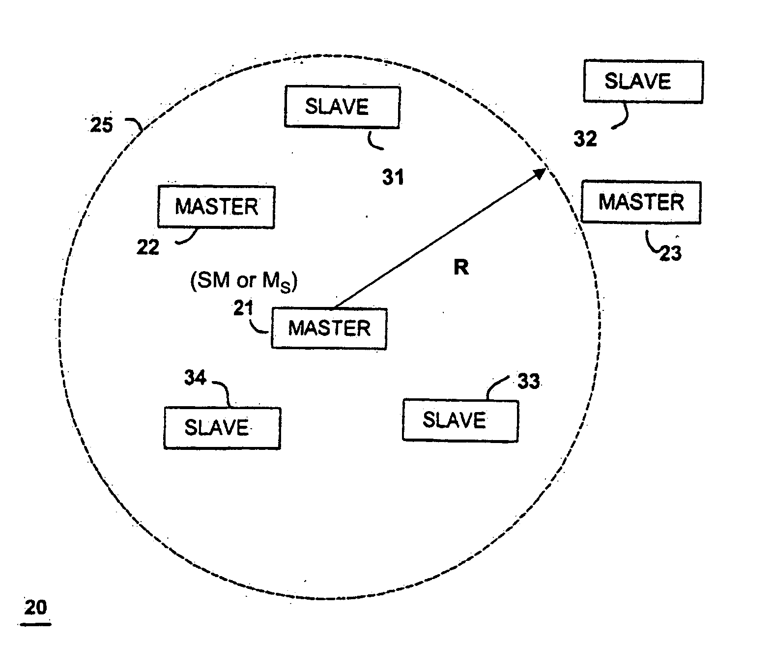
[0062] Referring to FIG. 1, a tracking and locating system 20 is illustrated according to an exemplary embodiment of the present invention for finding, locating, monitoring and or tracking of at least one target (T) that can be animate or inanimate, or both. The tracking and locating system 20 and method is described herein in several exemplary embodiments that have application for finding the location of a target T and or for allowing tracking of numerous targets T in different contexts. The method and system of the present invention is not limited to such enumerated exemplary embodiments in the different contexts as it should be appreciated that techniques and devices of the tracking and locating system 20 can be used for tracking and locating other animate things and or subjects such as pets and other animals. The method, techniques and tracking and locating system 20 can be used in locating inanimate things and subjects such as keys, eyeglasses, wallets, purses, portable telepho...


PUM


Abstract

A wireless system and method for determining the location of a fixed or mobile subject or object includes a transponder disposed on the target, a transceiver for monitoring the location of the target, a wireless communication system operating on at least one Radio Frequency (RF) band configured to allow communication between the transponder and the transceiver, and a processor configured to find the target by virtual triangulation based on values of position information received from the transponder and the transceiver. The processor is configured to determine virtual triangulation based on successive values of the position information using at least three points P1, P2 and P3 of the transponder respective of the transceiver. The processor can include a means for position ambiguity reduction (PAR) configured to find the target by correcting the direction to the location of the target T based on the values of the position information. The processor can also determine the position of the target based on the average speed of the motion of the user of the transponder respective of the transceiver. Furthermore, the processor can determine virtual triangulation based on successive values of the position information from user input on the transceiver. The method finding the target T (“finder” techniques) based on one or more position determination principles including determining the position of the target using virtual triangulation between the master or monitoring unit and at least one target T, whereby the monitoring device Ms measures the distance between it and the slave unit and, alternatively, in addition to measuring the distance between itself and the slave unit, between itself and another monitoring unit, or the monitoring device Ms measures the distance between its own successive locations. The present invention also discloses methods for finding with virtual triangulation by: (1) finding with virtual triangulation by generating position information in real-time, in the case of (i) stationary and moving target, and or (ii) in the case of the presence of obstacles; (2) finding with virtual triangulation relating to the average speed of the motion of operator; and or (3) finding with simplified virtual triangulation, whereby the user-device interaction is minimized—eliminating the need for monitoring device Ms to measure the distance between its own successive locations as well as the user's signaling to the monitoring or master unit when in motion or during stops.

Description

[0001] This application claims the benefit of United States Provisional Patent Application No. 60 / 449,702 filed Feb. 24, 2003.BACKGROUND OF THE INVENTION [0002] 1. Field of the Invention [0003] The present invention relates generally to locator systems and techniques, and more particularly, to finding systems for determining the location of objects and / or subjects. [0004] 2. Description of the Related Art. [0005] Most systems for locating a subject or object employ the use of direction locating antennas to determine the position of the subject. However, such locating systems are characterized by shortcomings associated with the size of the antenna at the bandwidth that is optimal for the application. Direction locating antennas experience significant degradation of directional capabilities in close range conditions wherein the separation between a search unit and a target is about several hundred feet or less. [0006] It is well known that there is a correlation between antenna size ...

Claims


Application Information

Patent Timeline
IPC IPC(8): G08B1/08
CPCG01S13/74G01S13/87G01S13/84
Inventor MARKHOVSKY, RUSSOSPOV, SERGEIVITYAEV, EVOENIIMIXHIENKU, EVOENIITIURLIKOV, ANDREYIVANIYA, SERGEIMARKHOVSKY, STANISLAV
Owner QUALCOMM TECHNOLOGIES INC
Why Eureka
Try Eureka