Methods and apparatus for refractive flow measurement

a refractive flow and measurement method technology, applied in the field of methods and apparatus for refractive flow measurement, can solve the problems of limited in-lab use, difficult to apply this technique outside of the laboratory setup, and complicated or expensive setups

Active Publication Date: 2015-01-15
MASSACHUSETTS INST OF TECH
View PDF3 Cites 15 Cited by
  • Summary
  • Abstract
  • Description
  • Claims
  • Application Information

AI Technical Summary

Problems solved by technology

For example, they are often based on complicated or expensive setups or are limited to in-lab use.
Thus, it can be difficult to apply this technique outside of the laboratory setup.
Moreover, foreign substance techniques require the cost and inconvenience of seeding a fluid with particles, may be limited to special studies, and is not suitable for monitoring in everyday use.
Moreover, the core assumption of brightness constancy on which standard optical flow techniques are based does not hold for a refractive fluid.
The failure of the brightness constancy assumption can lead to both incorrect magnitude of motion and incorrect direction of motion for standard fluid flow calculations.

Method used


Image

  • Methods and apparatus for refractive flow measurement
  • Methods and apparatus for refractive flow measurement
  • Methods and apparatus for refractive flow measurement

Examples


Embodiment Construction

[0053]A description of example embodiments of the invention follows.

[0054]The teachings of all patents, published applications and references cited herein are incorporated by reference in their entirety.

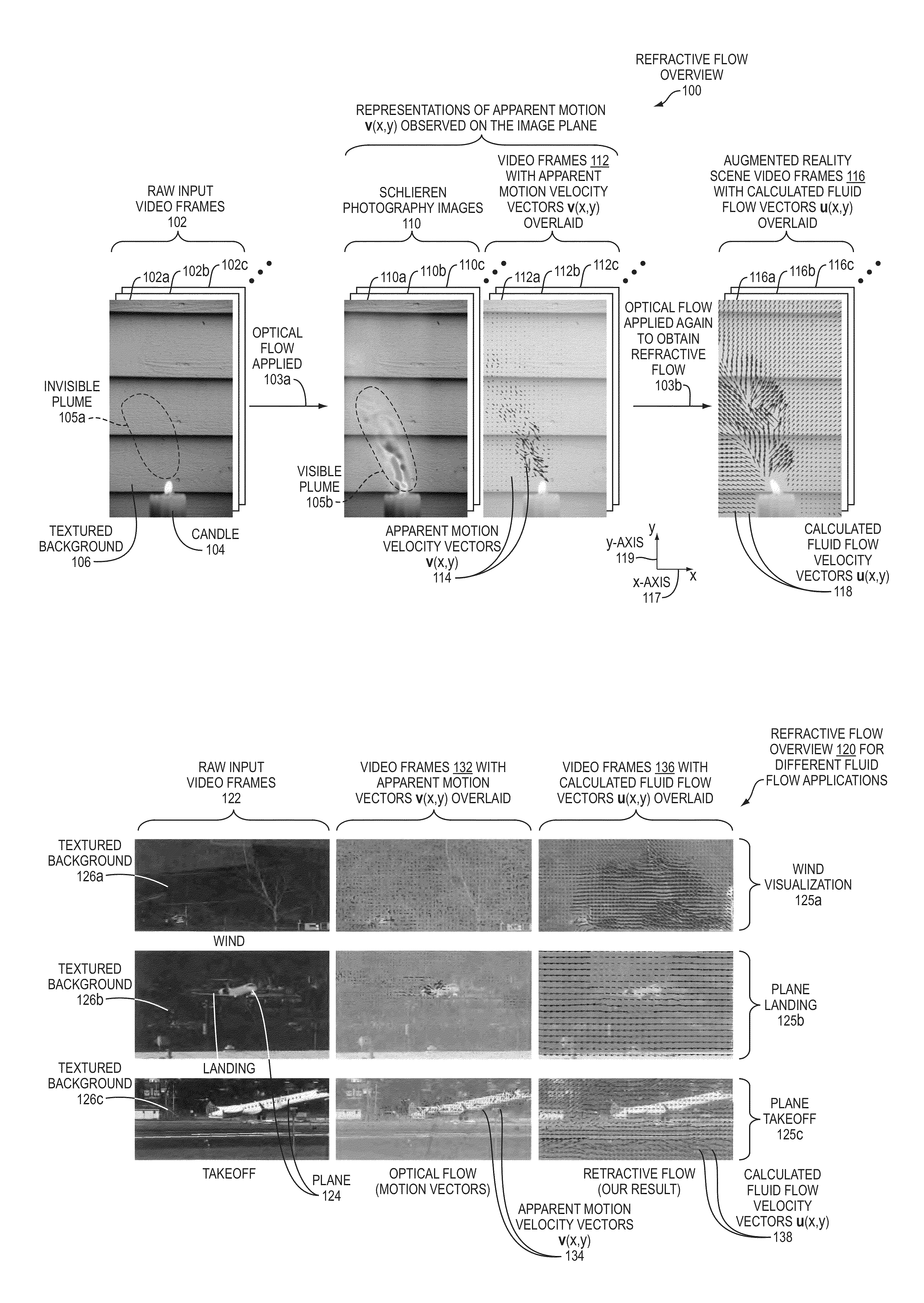
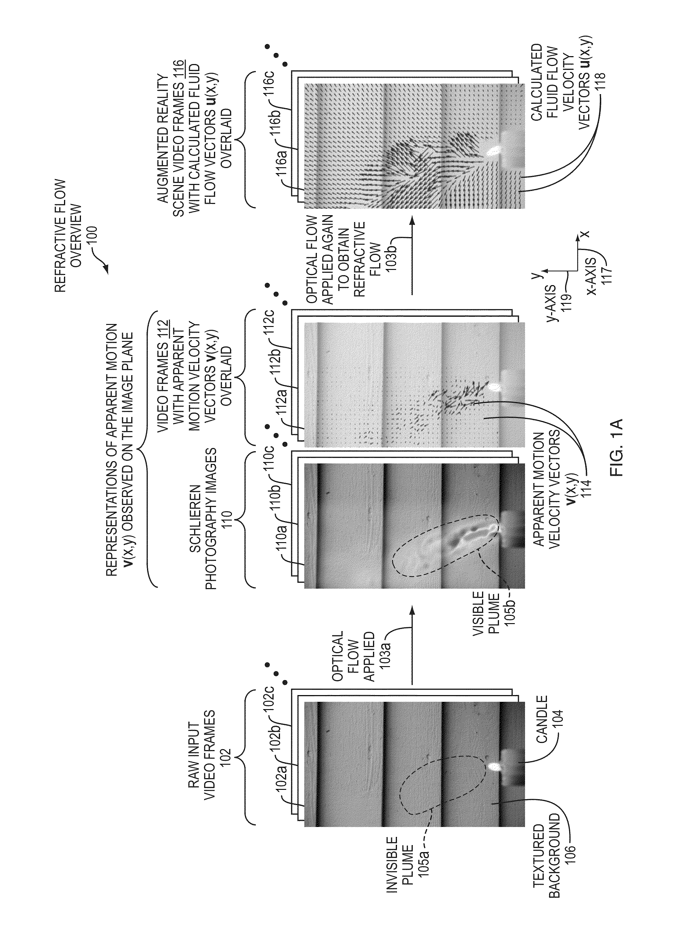
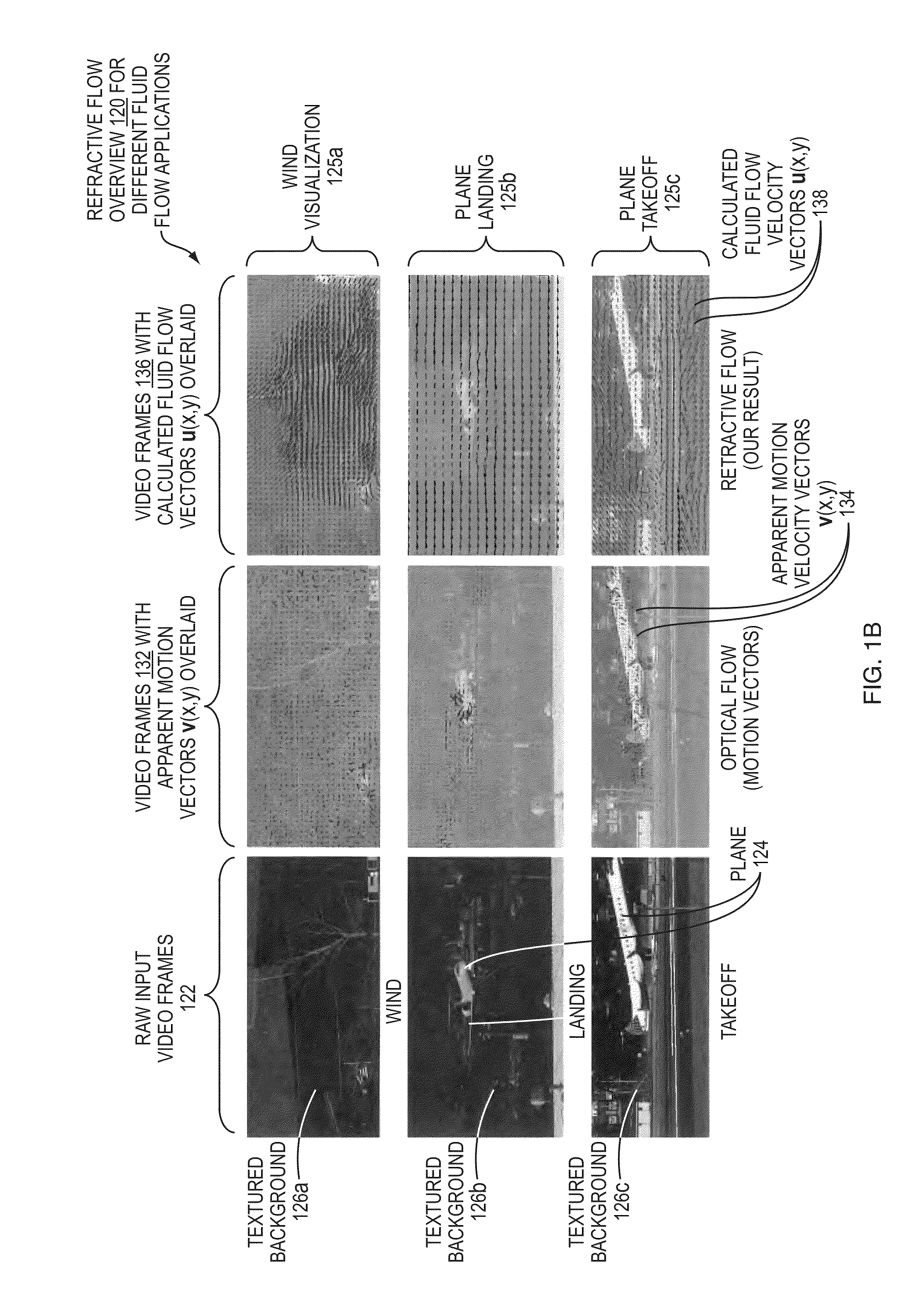
[0055]Measuring and visualizing how air and fluid move is of great importance, and has been the subject of study in broad areas of science and technology, including aeronautical engineering, combustion research, and ballistics. Special techniques may be necessary to visualize fluid flow, and an example is shown in FIG. 1A.

[0056]FIG. 1A shows images 102 of a burning candle 104. A plume 105a of the candle 104 is invisible to the naked eye and to standard video techniques. The heat rising from the burning candle 104 causes small, invisible distortions of a textured background 106 seen behind the candle 104. The small distortions of the background result from light rays being refracted by the plume 105a as they travel from the background 106 to a camera (not shown). As the air in the can...


PUM


Abstract

An imaging method and corresponding apparatus according to an embodiment of the present invention enables measurement and visualization of fluid flow. An embodiment method includes obtaining video captured by a video camera with an imaging plane. Representations of motions in the video are correlated. A textured background of the scene can be modeled as stationary, with a refractive field translating between background and video camera. This approach offers multiple advantages over conventional fluid flow visualization, including an ability to use ordinary video equipment outside a laboratory without particle injection. Even natural backgrounds can be used, and fluid motion can be distinguished from refraction changes. Depth and three-dimensional information can be recovered using stereo video, and uncertainty methods can enhance measurement robustness where backgrounds are less textured. Example applications can include avionics and hydrocarbon leak detection.

Description

RELATED APPLICATION[0001]This application claims the benefit of U.S. Provisional Application No. 61 / 980,521, filed on Apr. 16, 2014 and U.S. Provisional Application No. 61 / 823,580, filed on May 15, 2013. The entire teachings of the above applications are incorporated herein by reference.GOVERNMENT SUPPORT[0002]This invention was made with government support under Contract No. N00014-10-1-0951 awarded by the U.S. Navy. The government has certain rights in the invention.BACKGROUND OF THE INVENTION[0003]Measurement and visualization of air and fluid movement is useful in such areas as aeronautical engineering, combustion research, and ballistics. Various techniques have been proposed for measuring and visualizing fluid motion, and they can be based on computation of optical flow in a video using an assumption of brightness constancy. Previously proposed techniques have included sound tomography, Doppler LIDAR, and schlieren photography.[0004]Two general techniques to visualize and meas...

Claims


Application Information

Patent Timeline
Patent Type & Authority Applications(United States)
IPC IPC(8): G06T7/20
CPCG06T2207/10016G06T7/20G01P5/001G01P5/26G06T2207/10021G06T7/246G06T2207/10056G06T2207/30241G02B27/54
Inventor FREEMAN, WILLIAM T.DURAND, FREDERICXUE, TIANFANRUBINSTEIN, MICHAELWADHWA, NEAL
Owner MASSACHUSETTS INST OF TECH
Why Eureka
Try Eureka