Press felt for a papermaking machine

a papermaking machine and felt technology, applied in the field of press felt, can solve the problems of reducing the water take-up capacity of the felt, reducing the void volume, and the above described attempts were only in some cases successful, and achieve the effect of improving compressive resilience and compaction resistance properties

Active Publication Date: 2015-01-22
VOITH PATENT GMBH
View PDF1 Cites 0 Cited by
  • Summary
  • Abstract
  • Description
  • Claims
  • Application Information

AI Technical Summary

Benefits of technology

[0021]Alternate embodiments of the invention are further explained in the subclaims.
[0022]According to another embodiment of the invention, the beads or strands project in height above the at least one side of the base structure to which they have been applied and/or at least partially penetrate from the at least one side of the base structure to which they have been applied into the base structure.
[0023]According to a further embodiment of the present invention, the polymeric beads or strands have a longitudinal expansion at least partially in the cross machine direction of the felt. According to this embodiment, the polymeric beads or strands extend at least partially along their longitudinal expansion in a direction having a component in the machine direction of the felt and a component in the cross machine direction of the felt, as it might be, if the beads or strands extend in diagonal or curved lines.
[0024]According to a further embodiment of the present invention, the polymeric beads or strands form curved and/or straight lines at least partially along their longitudinal expansion. The polymeric beads or strands forming the curved lines can, for example, form a wavy line pattern on the base structure of the press felt. The polymeric beads or strands forming straight lines at least partially along their longi

Problems solved by technology

After several hundred thousand of compaction-expansion cycles the degree of recovery of the felt to its original thickness reduces irreversibly, leading to reduced void v

Method used


Image

  • Press felt for a papermaking machine
  • Press felt for a papermaking machine
  • Press felt for a papermaking machine

Examples


Embodiment Construction

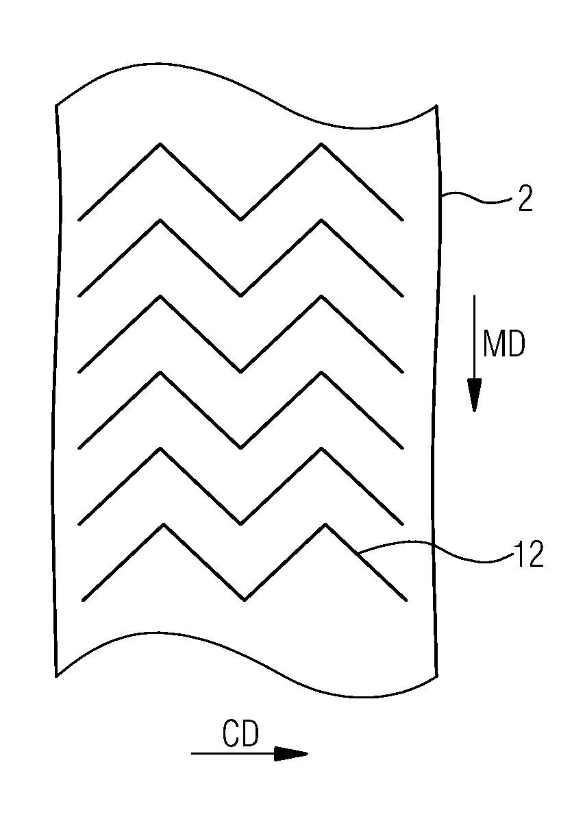
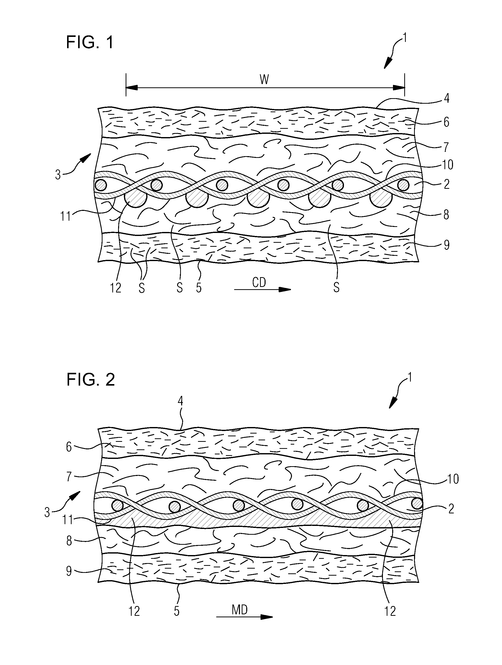
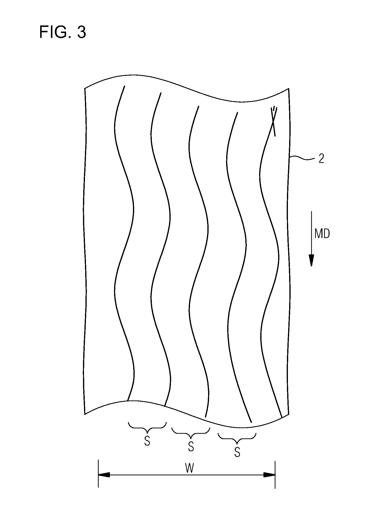
[0060]Referring now to FIG. 1, a cross sectional view in a cross machine direction CD of a press felt 1 according to an embodiment of the present invention is shown. The press felt 1 has a woven base structure 2 that provides the dimensional stability at least in a machine direction MD and the cross machine direction CD of the felt 1 and a batt fiber structure 3 with a plurality of batt fiber layers 6, 7, 8, 9 attached to the base structure 2 that provides a paper contacting side 4 and a machine contacting side 5 of the felt 1.

[0061]The batt fiber structure 3 of the embodiment as shown by press felt 1 of FIGS. 1 and 2 is made of the four batt fiber layers 6, 7, 8 and 9. The batt fiber layers 6 and 7 are attached to the base structure 1 on a first side 10 of the base structure 2 which is facing to the paper contacting side 4 and the batt fiber layers 8 and 9 are attached to a second side 11 of the base structure 2 which is facing to the machine contacting side 5.

[0062]According to an...


PUM

PropertyMeasurementUnit
Lengthaaaaaaaaaa
Lengthaaaaaaaaaa
Lengthaaaaaaaaaa

Abstract

A press felt includes a base structure providing dimensional stability in a machine and a cross machine direction of the felt, a batt fiber structure including batt fiber layers attached to the base structure which provide a paper contacting side and a machine contacting side of the felt. The base structure includes a first and second side. Polymeric beads or strands made from a polymeric material are arranged on at least one of the two sides of the base structure. The polymeric beads or strands arranged on the at least one side have a longitudinal expansion in the machine direction of the felt and are arranged side-by-side when viewed in the cross machine direction of the felt to generate space between adjacent beads or strands. At least one of the batt fiber layers is arranged to cover both the at least one side and the polymeric beads or strands thereon.

Description

CROSS REFERENCE TO RELATED APPLICATIONS[0001]This is a continuation of PCT application No. PCT / EP2013 / 057007, entitled “PRESS FELT FOR A PAPERMAKING MACHINE,” filed Apr. 3, 2013, which is incorporated herein by reference. PCT application No. PCT / EP2013 / 057007 is a PCT application based upon U.S. provisional patent application Ser. No. 61 / 620,818, entitled “PRESS FELT FOR A PAPERMAKING MACHINE,” filed Apr. 5, 2012, which is incorporated herein by reference.BACKGROUND OF THE INVENTION[0002]1. Field of the Invention[0003]The invention relates to a press felt for use in a press section of a paper, board or tissue machine.[0004]2. Description of the Related Art[0005]Press felts known in the art comprise a base structure which provides the dimensional stability of the felt and a batt fiber structure which is normally attached to the base structure by needling and which provides a paper and a machine contacting side of the felt.[0006]During operation especially, the batt fiber structure is...

Claims


Application Information

Patent Timeline
IPC IPC(8): B32B37/24D21F7/08B32B37/18
CPCD21F7/08B32B37/24B32B2305/30B32B2305/28B32B37/18D21F7/083
Inventor MORTON, ANTONYPONTON, DAVID STUARTRIDING, PAUL RAYMONDALLUM, ANDREW
Owner VOITH PATENT GMBH
Why Eureka
Try Eureka