
Self-righting means for leaning vehicles; primarily by gravity

a technology of leaning vehicles and self-righting means, applied in the field of self-righting means for leaning vehicles, can solve the problems the center of gravity falling, etc., and achieve the effect of raising the cg and and reducing the energy state of the vehicl

Inactive Publication Date: 2015-01-22
LIN JAMES
View PDF11 Cites 7 Cited by
  • Summary
  • Abstract
  • Description
  • Claims
  • Application Information

AI Technical Summary

Benefits of technology

The present invention provides a vehicle with a segmented body structure that is designed to raise the vehicle's Center of Gravity (CG) and energy state as it leans. This prevents the vehicle from falling to the ground and allows it to return to its original stable upright position. The result is a zero net energy loss when the vehicle leans, achieved by raising the CG while the vehicle is still leaning. This vehicle design maintains stability and energy while in a variety of leaning angles.

Problems solved by technology

Typically, when a vehicle leans, its Center of Gravity (CG) falls and reduces that vehicle's energy state.

Method used


Image

  • Self-righting means for leaning vehicles; primarily by gravity
  • Self-righting means for leaning vehicles; primarily by gravity
  • Self-righting means for leaning vehicles; primarily by gravity

Examples


Embodiment Construction

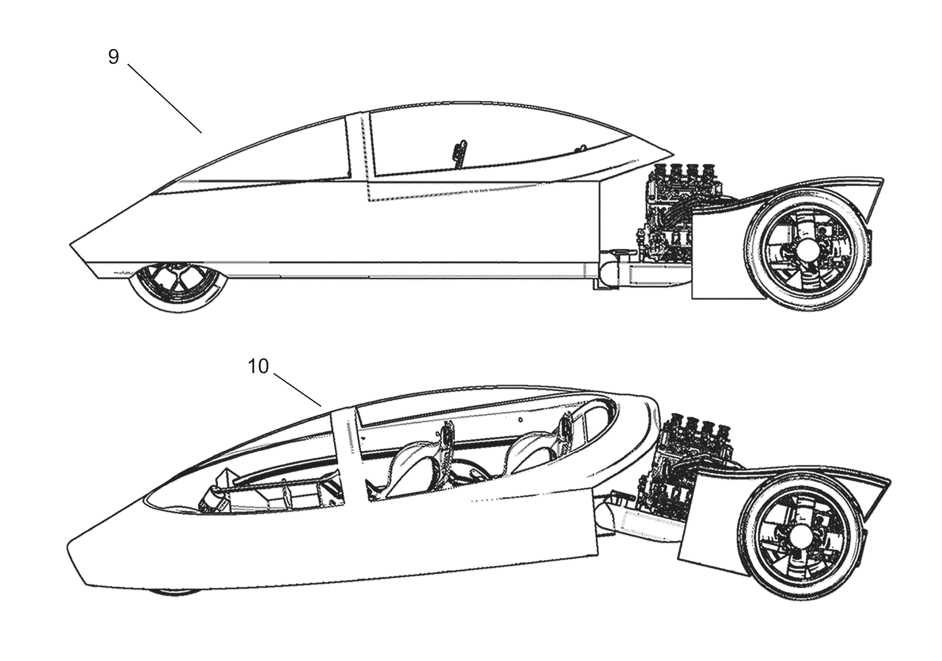
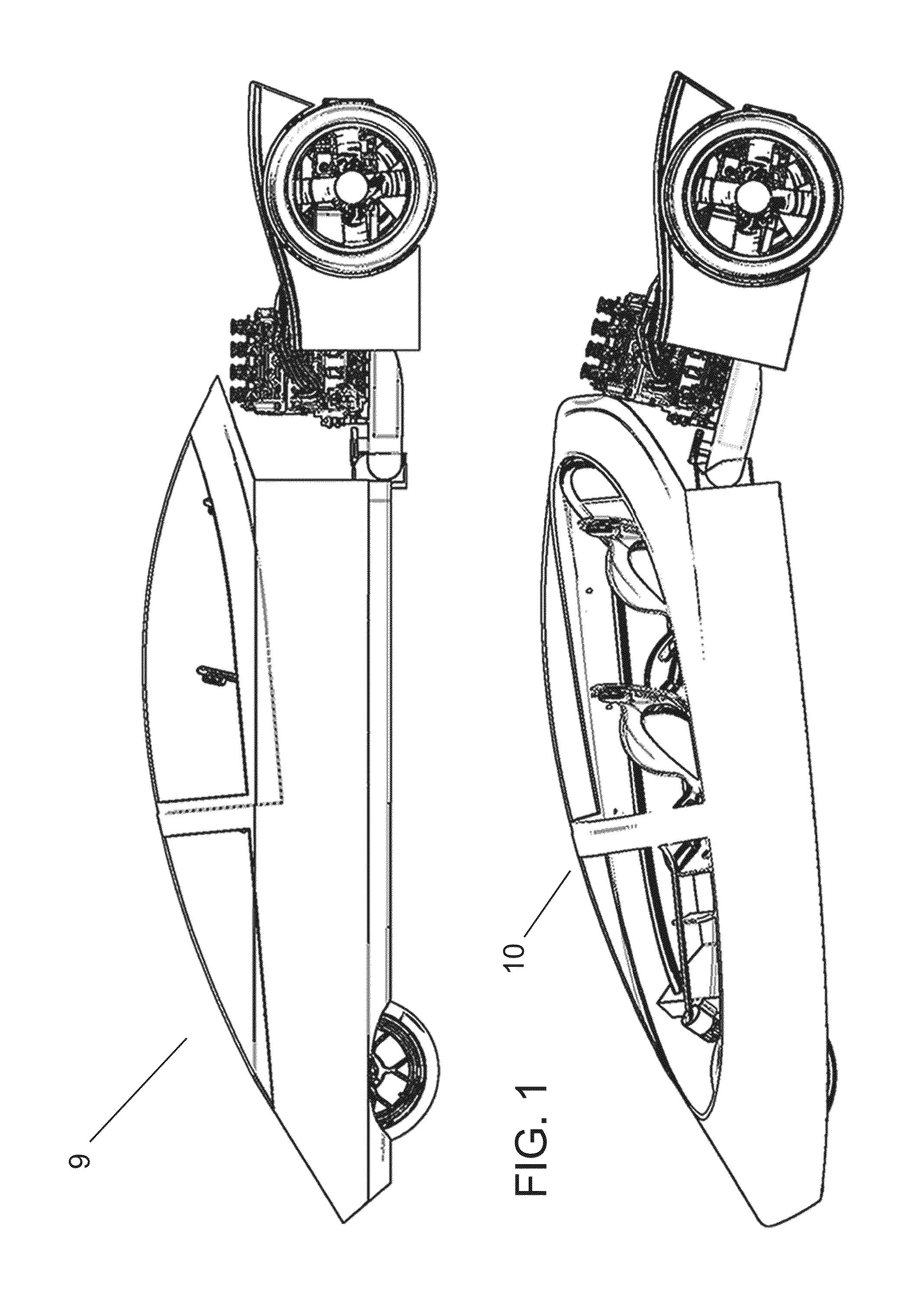
[0030]FIG. 1 shows the side views of the upright segmented vehicle 9 (top) and the leaning segment vehicle 10 (bottom) to illustrate how the segmented vehicle bends to raise its CG in the two configurations for this preferred embodiment.

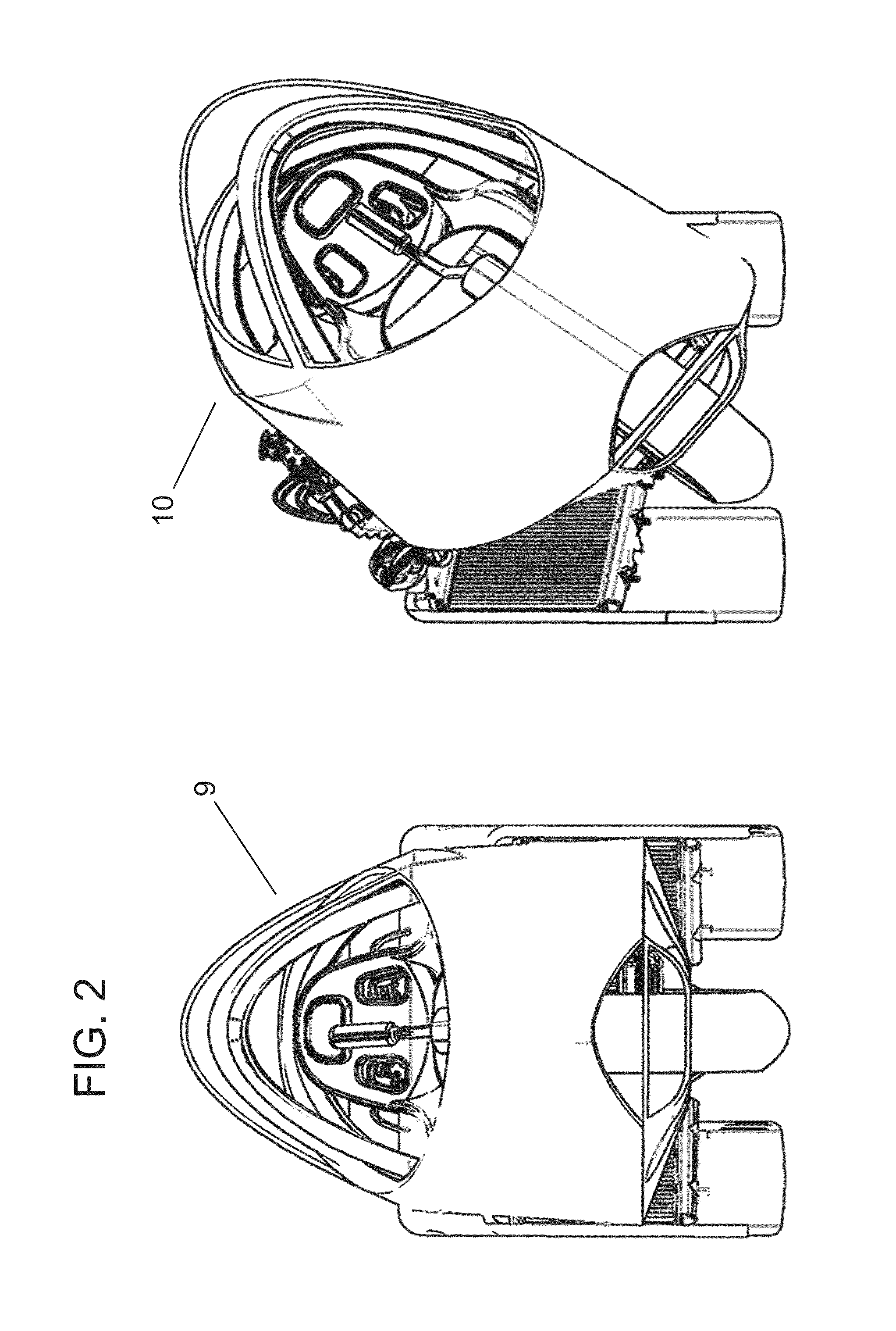
[0031]FIG. 2 shows the front views of the upright segmented vehicle 9 (left) and the leaning segment vehicle 10 (right) to illustrate how the segmented vehicle bends in the two configurations.

[0032]FIG. 3 is a comparison of the typical motorcycle 11's Center of Gravity (CG) CG 1 location versus the preferred embodiment's segmented vehicle 9's CG 1. For each vehicle, the CG 1 is the concentration of mass acting on the moment arm 2 whose fulcrum is in line with the wheels' contact line.

[0033]FIG. 4 shows the basic dynamic forces involved with the leaning vehicle—here the typical motorcycle 11.

[0034]FIG. 5 shows the same forces acting on the segmented vehicle 9.

[0035]Finally, for clarity, FIG. 6 illustrates only the leaning vehicle forces involved (line...


PUM


Abstract

A low cost leaning vehicle stability and self-righting system that primarily uses gravity to return a leaning vehicle position to its original stable upright position. The system accomplishes this by increasing the leaning vehicle's Center of Gravity (CG) above the resting upright position—thus increasing the CG energy state—the more the vehicle leans. The system stores energy—a combination of additional and recovered energy normally lost when the vehicle leans—primarily in the form of gravitational potential energy to automatically return the vehicle from a leaning position to the upright stable position.

Description

CROSS-REFERENCE TO RELATED APPLICATIONS[0001]This application claims the benefit of provisional application Ser. No. 61 / 674,341 filed on Jun. 21, 2012.BACKGROUND[0002]1. Prior Art[0003]The following is a tabulation of some prior art that presently appears relevant:U.S. PatentsPatent NumberKind CodeIssue DatePatentee21529381939 April 4 Welch23535031944 July 11Rost27439411956 May 1 Walker32856231956 November 15Winsen36012131971 August 24 Patin37461181973 July 17Altorfer40209141977 May 3 Trautwein40651441977 December 27Winchell40723251978 February 7Bright43456611982 August 24Nishikawa43514101982 September 28Townsend44693441984 September 4 Coil44874291984 December 11Ruggles46244691986 November 25 Bourne, Jr.46324131986 December 30Fujita46608531987 April 28Jephcott49038571990 February 27Klopfenstein51160691992 May 26Miller56115551997 March 18Vidal57623511998 June 9 SooHoo57658461998 June 16Braun6328125B12001 December 11Van Den Brink6402174B12002 June 11Maurer6554293B12003 April 29Fennel7...

Claims


Application Information

Patent Timeline
IPC IPC(8): B60G21/00
CPCB60G21/005B60G2300/122B60G2300/45B60G2300/60B60G2400/63B62J27/00B62K5/10B62K5/027
Inventor LIN, JAMES
Owner LIN JAMES
Learn More