Mounting apparatus assembly

Inactive Publication Date: 2015-01-22
SCIENBIZIP CONSULTINGSHENZHENCO
View PDF28 Cites 8 Cited by
  • Summary
  • Abstract
  • Description
  • Claims
  • Application Information

AI Technical Summary

Benefits of technology

The patent is about a mechanism for moving a hard disc drive in a computer system. The mechanism includes a pivoting portion and a sliding portion that work together to move the drive in two directions. The mechanism also includes guiding slots and guiding parts that work together to ensure smooth movement of the hard disc drive. The technical effect of this mechanism is improved performance and reliability of the hard disc drive in computer systems.

Problems solved by technology

Fixing the hard disc drives to the bracket may be laborious and time consuming.

Method used


Image

  • Mounting apparatus assembly
  • Mounting apparatus assembly
  • Mounting apparatus assembly

Examples


Embodiment Construction

[0011]The disclosure is illustrated by way of example and not by way of limitation in the figures of the accompanying drawings in which like references indicate similar elements. It should be noted that references to “an” or “one” embodiment in this disclosure are not necessarily to the same embodiment, and such references mean “at least one.”

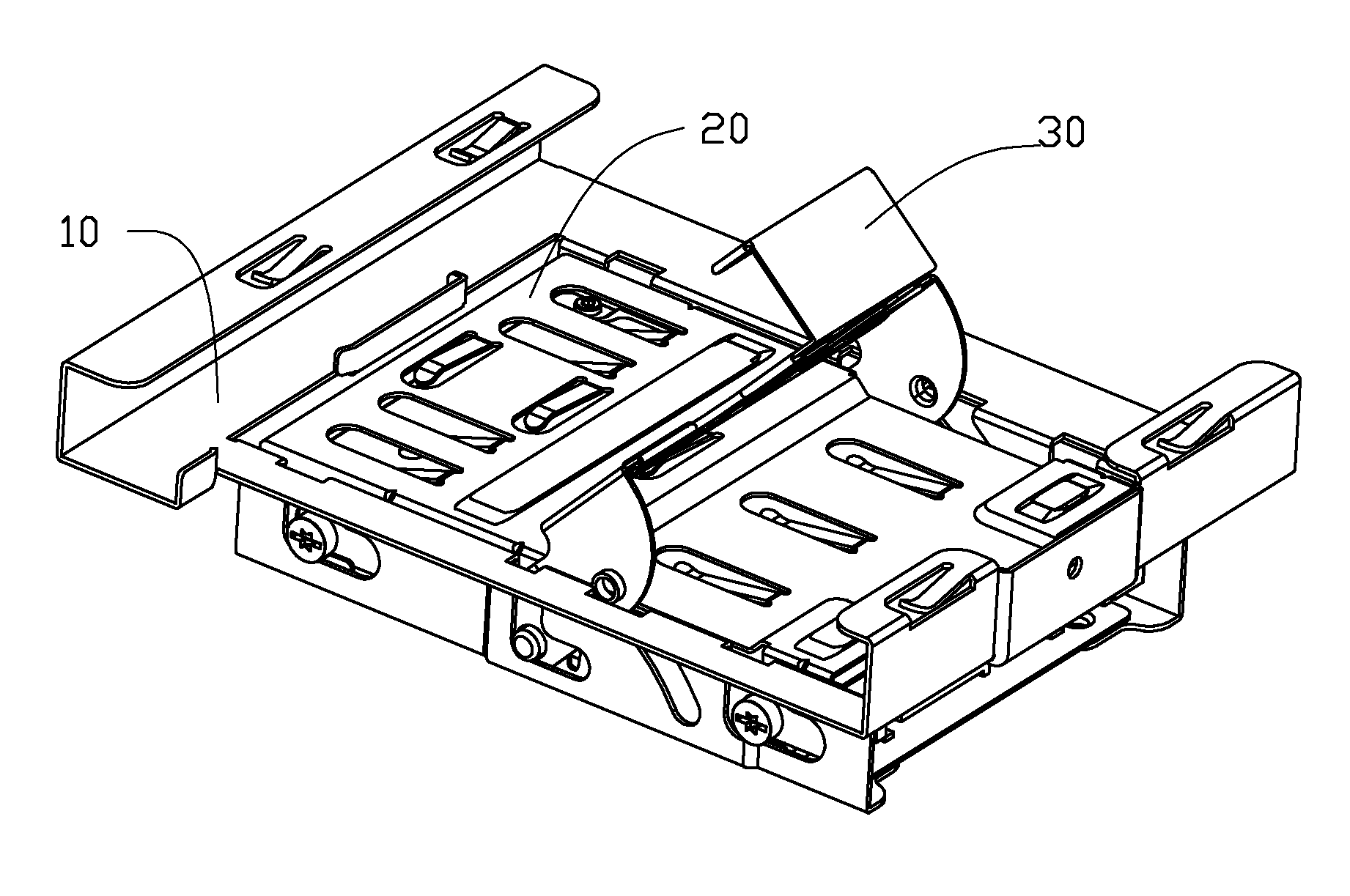
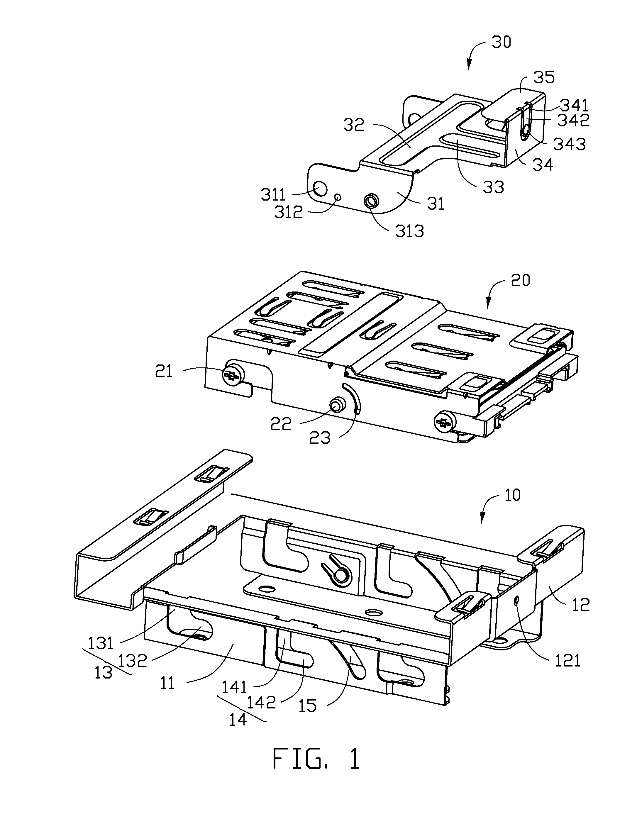
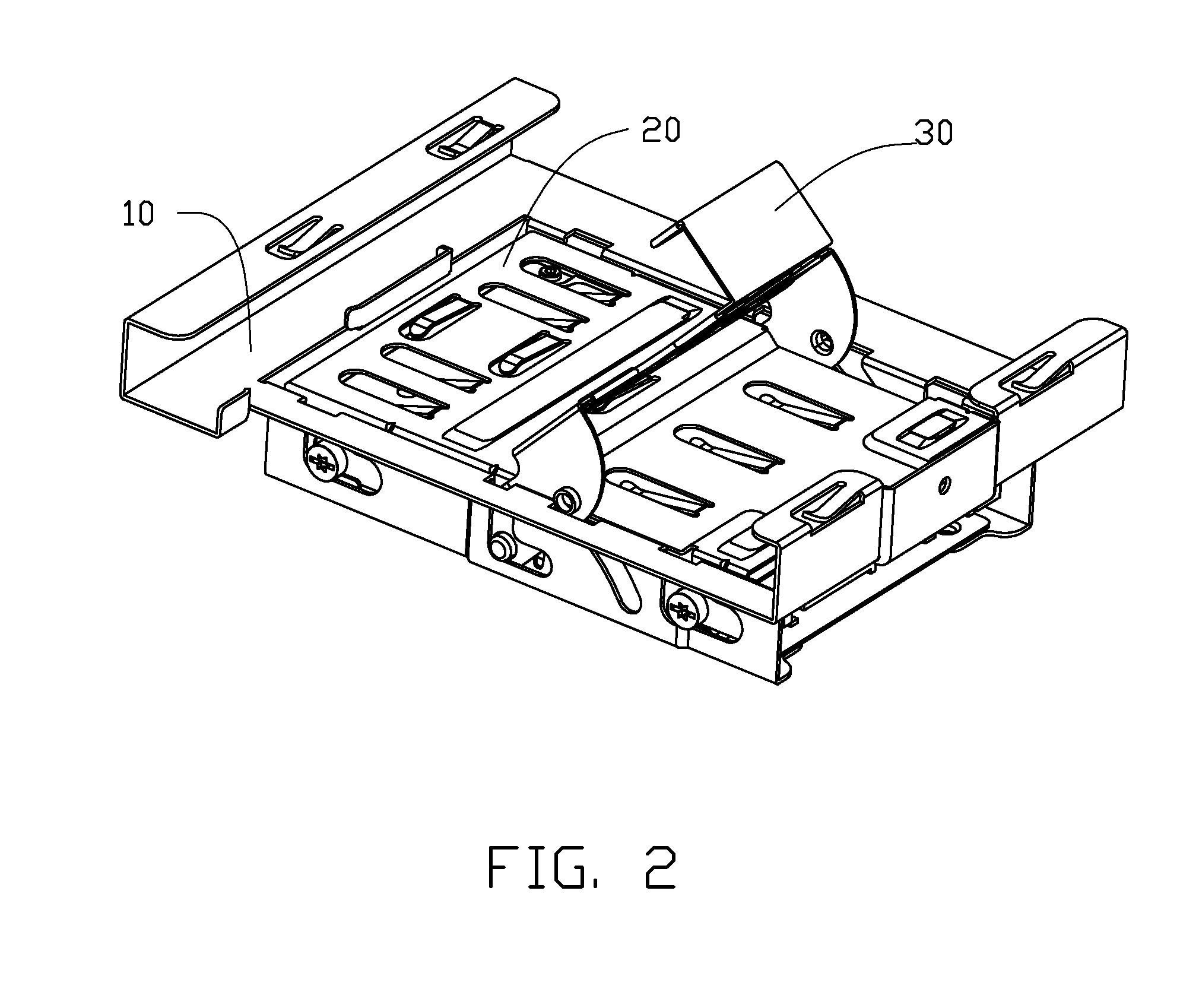
[0012]FIG. 1 shows a mounting apparatus assembly of the embodiment. The mounting apparatus assembly includes a bracket 10 for slidably receiving a hard disc drive 20. A pivoting member 30 is pivotally mounted to the hard disc drive 20.

[0013]The bracket 10 includes two side plates 11 and a connecting plate 12 connected to the two side plates 11. Two first sliding slots 13, a second sliding slot 14 and a first guiding slot 15 are defined in each of the two side plates 11. Each of the two first sliding slots 13 includes a first inserting portion 131 and a first sliding portion 132 communicating with the first inserting portion 131. The second slid...


PUM


Abstract

A mounting apparatus includes a bracket and a pivoting member. A first sliding slot, a second sliding slot, a first guiding slot and a locating hole are defined in the bracket. A pivoting hole, a first guiding portion, a second guiding portion and a resisting wall are located on the pivoting member. A locating block is positioned on the resisting wall. A fastening member and a pivoting portion are configured to be positioned on a hard disc drive. The pivoting portion is passed through the pivoting hole, the first guiding portion is slid in a second guiding slot in the hard disc drive, the fastening member is slid in the first sliding slot. The pivoting portion is slid in the second sliding slot, the second guiding portion is slid in the first guiding slot, the resisting wall is rotated until the locating block is locked in the locating hole.

Description

BACKGROUND[0001]1. Technical Field[0002]The present disclosure relates to a mounting apparatus assembly.[0003]2. Description of Related Art[0004]Conventional hard disc drives are fixed to a bracket of a computer case by rivets or screws. Fixing the hard disc drives to the bracket may be laborious and time consuming.[0005]Therefore, there is a need for improvement in the art.BRIEF DESCRIPTION OF THE DRAWINGS[0006]Many aspects of the embodiments can be better understood with reference to the following drawings. The components in the drawings are not necessarily drawn to scale, the emphasis instead being placed upon clearly illustrating the principles of the embodiments. Moreover, in the drawings, like reference numerals designate corresponding parts throughout the several views.[0007]FIG. 1 is an exploded view of an embodiment of a mounting apparatus assembly.[0008]FIG. 2 is an assembled view of the mounting apparatus assembly of FIG. 1.[0009]FIG. 3 is an isometric view of the mountin...

Claims


Application Information

Patent Timeline
IPC IPC(8): G11B33/02
CPCG11B33/02G11B33/022G06F1/187G11B33/124
Inventor DING, LINXIAO, YU-MING
Owner SCIENBIZIP CONSULTINGSHENZHENCO
Why Eureka
Try Eureka