Liquid ejecting apparatus and wiping method

a technology of liquid ejecting apparatus and wiping mechanism, which is applied in printing and other directions, can solve the problems of the head main body or the adhesive of the wiper to the side surface of the holder, and achieve the effect of preventing the adhesive from being adhered to the wiper

Active Publication Date: 2015-02-05
SEIKO EPSON CORP
View PDF2 Cites 3 Cited by
  • Summary
  • Abstract
  • Description
  • Claims
  • Application Information

AI Technical Summary

Benefits of technology

[0010]An advantage of some aspects of the invention is to provide a liquid ejecting apparatus and a wiping method by which a nozzle forming surface is effectively wiped by a wiper while liquid adhered to the wiper is inhibited from being adhered to a liquid ejecting unit side.
[0013]According to this aspect, the interference amount of the wiper and the nozzle forming surface in the position (the end portion of the nozzle forming surface) of the wiper which comes in contact with the liquid ejecting unit is the first interference amount which is smaller than the second interference amount, and thus the wiper is inhibited from being stroked in the position of the wiper which comes in contact with the liquid ejecting unit. For this reason, the liquid adhered to the wiper is inhibited from being adhered to the liquid ejecting unit side. On the other hand, since the interference amount of the wiper and the nozzle forming surface in the nozzle region of the nozzle forming surface is the second interference amount which is greater than the first interference amount, the nozzle forming surface is effectively wiped by the wiper. Therefore, it is possible to effectively wipe the nozzle forming surface by the wiper while the liquid adhered to the wiper is inhibited from being adhered to the liquid ejecting unit side.
[0015]According to this aspect, in particular, it is possible to effectively wipe the nozzle region of the nozzle forming surface by the wiper.
[0017]According to this aspect, a contact amount of the wiper and the scraping unit becomes larger, and thus it is possible to effectively scrape off and collect the liquid adhered to the wiper by the scraping unit.
[0019]According to this aspect, it is possible to change the interference amount of the wiper and the nozzle forming surface from the first interference amount to the second interference amount with high accuracy.
[0021]According to this aspect, the interference amount of the wiper and the nozzle forming surface in the position (the end portion of the nozzle forming surface) of the wiper which comes in contact with the liquid ejecting unit is the first interference amount which is smaller than the second interference amount, and thus the wiper is inhibited from being stroked in the position of the wiper which comes in contact with the liquid ejecting unit. For this reason, the liquid adhered to the wiper is inhibited from being adhered to the liquid ejecting unit side. On the other hand, since the interference amount of the wiper and the nozzle forming surface in the nozzle region of the nozzle forming surface is the second interference amount which is greater than the first interference amount, the nozzle forming surface is effectively wiped by the wiper. Therefore, it is possible to effectively wipe the nozzle forming surface by the wiper while the liquid adhered to the wiper is inhibited from being adhered to the liquid ejecting unit side.

Problems solved by technology

For this reason, the wiper is stroked by the corner portion of the holder or the corner portion of the head main body, so that a problem in which the ink adhered to the wiper is adhered to a side surface of the holder or the head main body occurs.
Furthermore, these problems are not limited to an ink jet-type printer but are substantially common to liquid ejecting apparatuses provided with a wiper for sweeping away liquid adhered to a nozzle forming surface of a liquid ejecting head.

Method used


Image

  • Liquid ejecting apparatus and wiping method
  • Liquid ejecting apparatus and wiping method
  • Liquid ejecting apparatus and wiping method

Examples


modification example

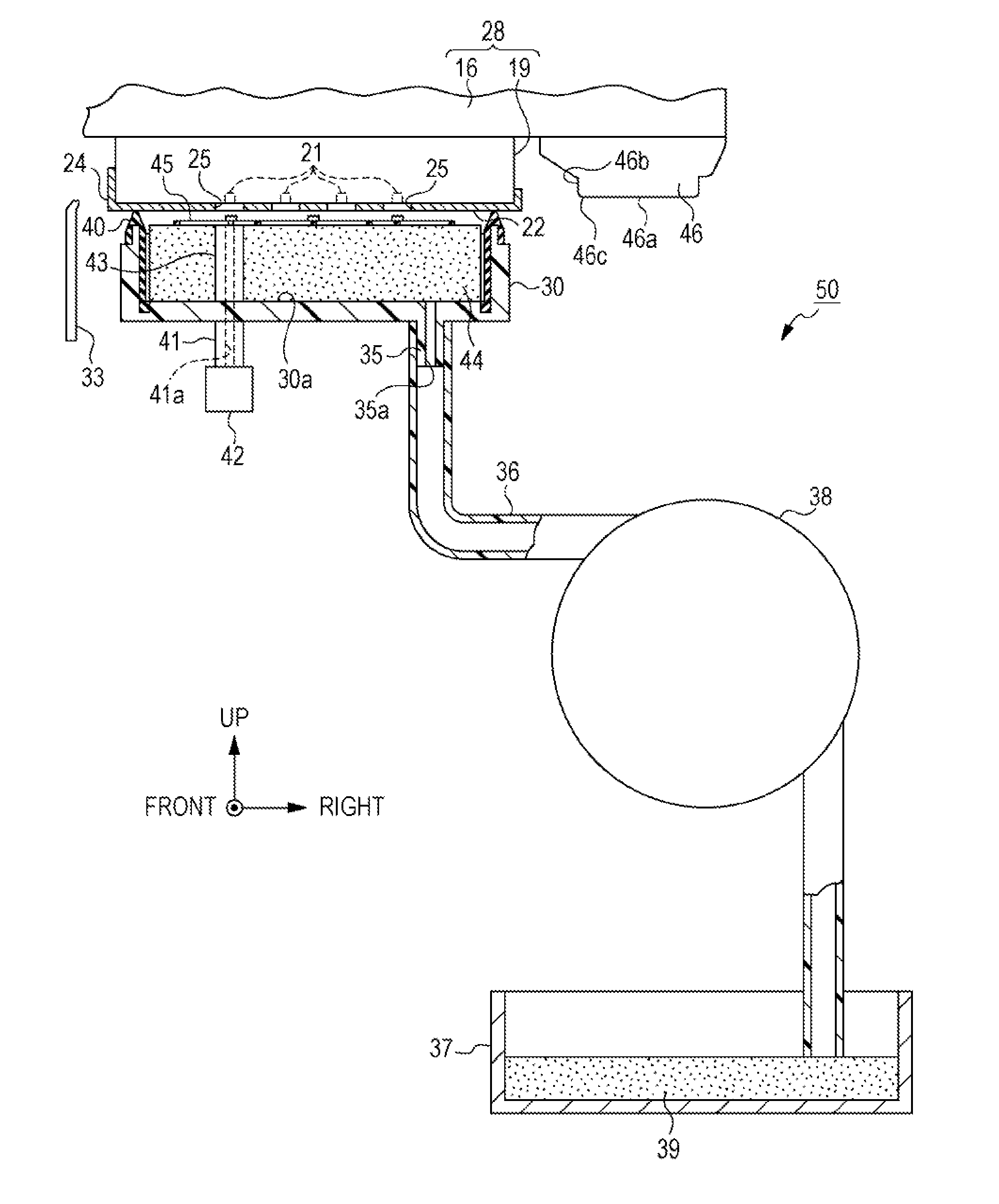
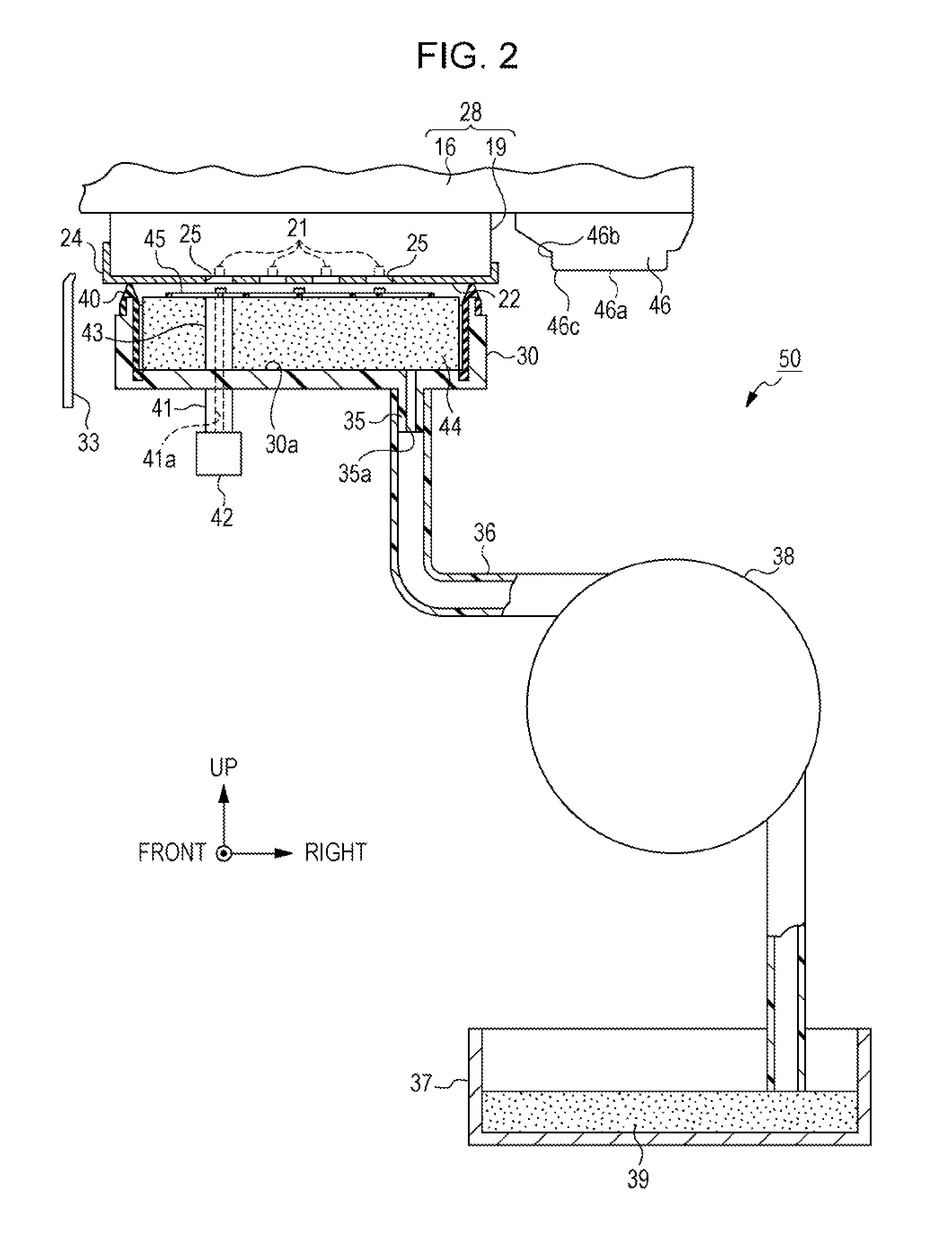
[0081]Furthermore, the embodiment described above may be modified as following.[0082]The operation for changing the interference amount of the wiper 33 and the nozzle forming surface 22 in the vertical direction from the first interference amount to the second interference amount which is greater than the first interference amount, between the left end and the nozzle region NR of the nozzle forming surface 22 in the horizontal direction, may be performed while the carriage 16 is moved.[0083]The interference amount of the wiper 33 and the nozzle forming surface 22 in the vertical direction may not be changed to the third interference amount which is greater than the second interference amount, between the right end of the nozzle forming surface 22 and the scraping unit 46 in the horizontal direction.[0084]The operation for changing the interference amount of the wiper 33 and the nozzle forming surface 22 in the vertical direction to the third interference amount which is greater than...


PUM


Abstract

A liquid ejecting apparatus includes a liquid ejecting unit which includes a nozzle forming surface having nozzle openings for ejecting liquid formed thereon, a wiper which is contactably disposed on the nozzle forming surface, a movement unit which is able to relatively move the liquid ejecting unit and the wiper, and a control unit which controls the movement units such that an interference amount of the wiper and the nozzle forming surface in a position of the wiper which comes in contact with the liquid ejecting unit, is smaller than an interference amount of the wiper and the nozzle forming surface when the wiper is relatively moved through a nozzle region which is a region including the nozzle openings of the nozzle forming surface in a direction along the nozzle forming surface.

Description

BACKGROUND[0001]1. Technical Field[0002]The present invention relates to, for example, a liquid ejecting apparatus such as an ink jet-type printer, and a wiping method in the liquid ejecting apparatus.[0003]2. Related Art[0004]In general, as one type of a liquid ejecting apparatus, an ink jet-type printer in which printing is performed by ejecting ink (liquid) from a nozzle having an opening formed on a nozzle forming surface of a liquid ejecting head (a liquid ejecting unit) onto a recording medium such as paper is known. In such a printer, in order to maintain ejection properties of the ink from the liquid ejecting head, a head maintenance apparatus is generally provided.[0005]Such a head maintenance apparatus is provided with various functions. For example, a function in which a nozzle forming surface of a liquid ejecting head is capped by a suction cap, and thickened ink is sucked from a nozzle by a suction pump, thereby allowing the ejection properties of the ink from the nozzl...

Claims


Application Information

Patent Timeline
Patent Type & Authority Applications(United States)
IPC IPC(8): B41J2/165
CPCB41J2/16535B41J2/16541B41J2/16538
Inventor MANO, TAKASHI
Owner SEIKO EPSON CORP
Why Eureka
Try Eureka