Transform Encoding/Decoding of Harmonic Audio Signals

a technology of harmonic audio signal and transform encoding, applied in the field of transform encoding/decoding of harmonic audio signal, can solve the problems of inadequacies, single instruments, and inability to produce acceptable quality residual encoding schemes, and achieve the effect of improving perceptual quality

Active Publication Date: 2015-02-12
TELEFON AB LM ERICSSON (PUBL)
View PDF14 Cites 12 Cited by
  • Summary
  • Abstract
  • Description
  • Claims
  • Application Information

AI Technical Summary

Benefits of technology

[0034]The proposed harmonic audio coding encoding/decoding scheme provides better percep...

Problems solved by technology

The conventional transform encoding concept does not work well with very harmonic audio signals, e.g. single instruments.
The reason is that the normalization with the spectrum envelope does not result in a sufficiently “flat” residual ...

Method used


Image

  • Transform Encoding/Decoding of Harmonic Audio Signals
  • Transform Encoding/Decoding of Harmonic Audio Signals
  • Transform Encoding/Decoding of Harmonic Audio Signals

Examples


Embodiment Construction

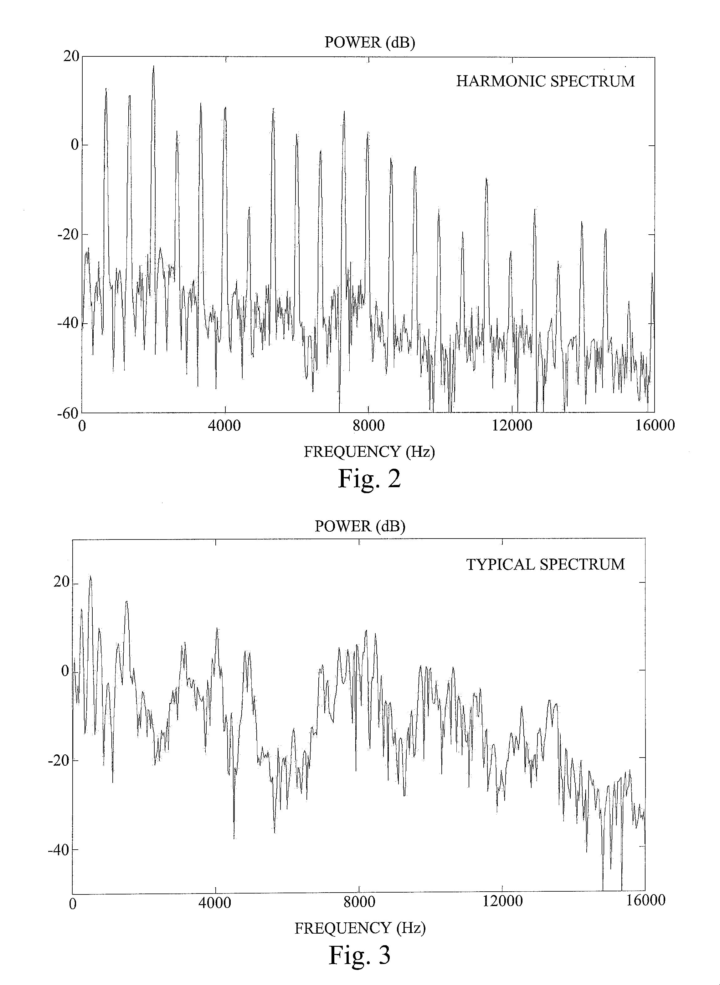
[0054]FIG. 2 illustrates a typical spectrum of a harmonic audio signal, and FIG. 3 illustrates a typical spectrum of a non-harmonic audio signal. The spectrum of the harmonic signal is formed by strong spectral peaks separated by much weaker frequency bands, while the spectrum of the non-harmonic audio signal is much smoother.

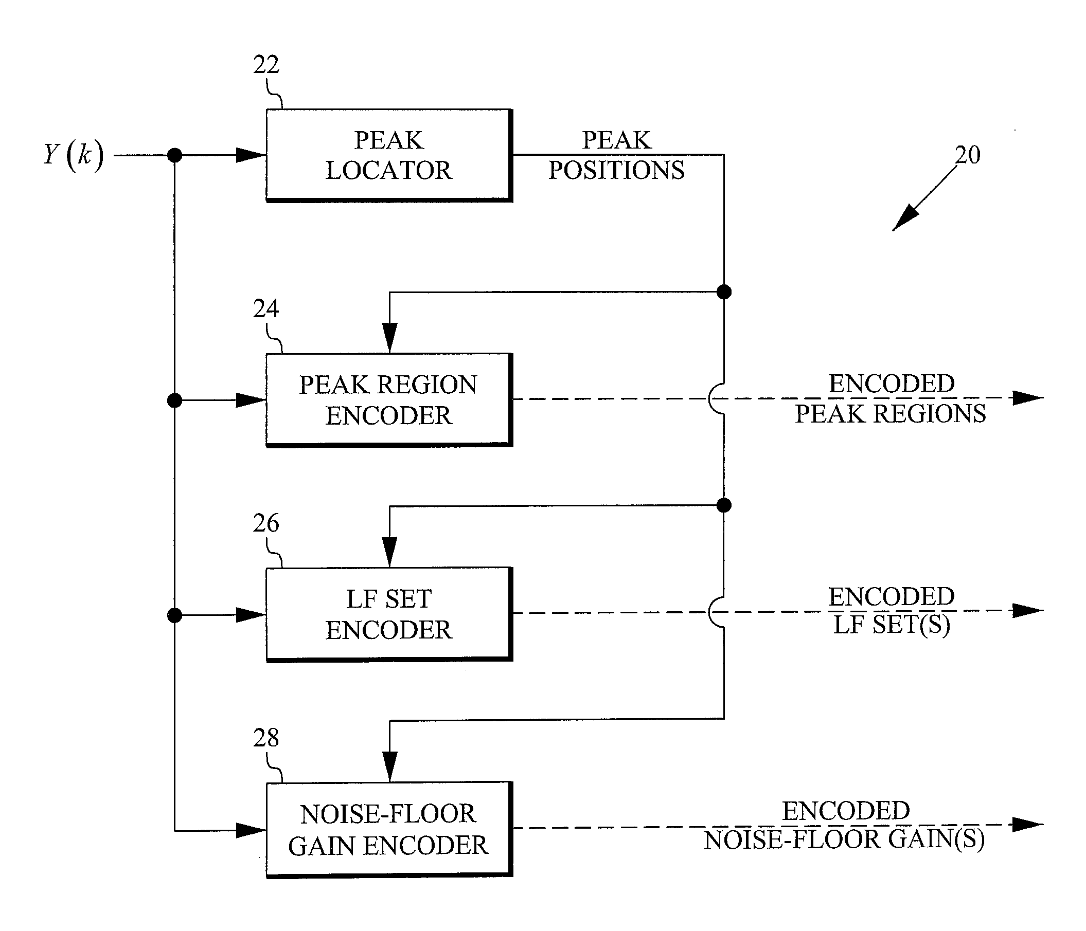
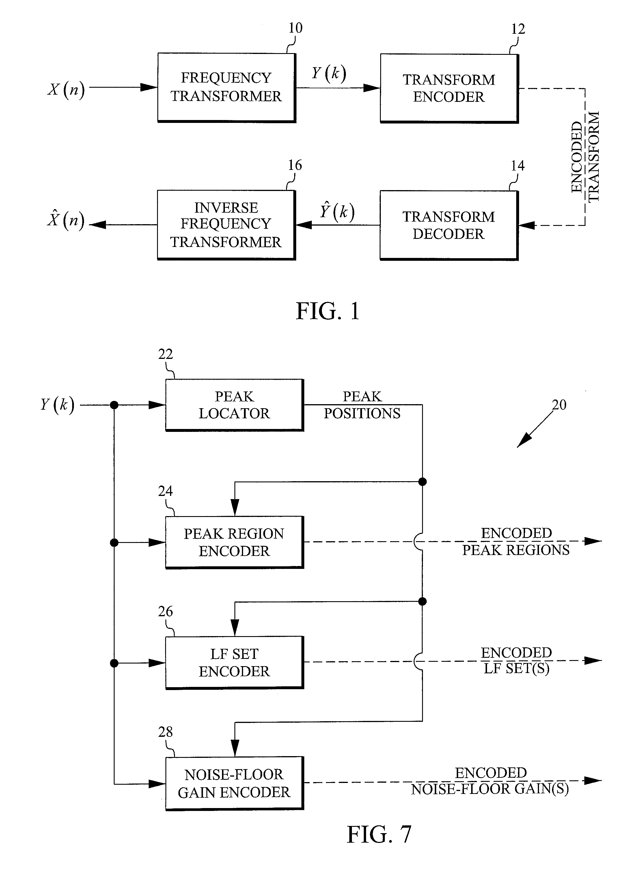
[0055]The proposed technology provides an alternative audio encoding model that handles harmonic audio signals better. The main concept is that the frequency transform vector, for example an MDCT vector, is not split into envelope and residual part, but instead spectral peaks are directly extracted and quantized, together with neighboring MDCT bins. At high frequencies, low energy coefficients outside the peaks neighborhoods are not coded, but noise-filled at the decoder. Here the signal model used in the conventional encoding, {spectrum envelope+residual} is replaced with a new model {spectral peaks+noise-floor}. At low frequencies, coefficients outside the pe...


PUM


Abstract

An encoder (20) for encoding frequency transform coefficients (Y(k)) of a harmonic audio signal include the following elements: A peak locator (22) configured to locate spectral peaks having magnitudes exceeding a predetermined frequency dependent threshold. A peak region encoder (24) configured to encode peak regions including and surrounding the located peaks. A low-frequency set encoder (26) configured to encode at least one low-frequency set of coefficients outside the peak regions and below a crossover frequency that depends on the number of bits used to encode the peak regions. A noise-floor gain encoder (28) configured to encode a noise-floor gain of at least one high-frequency set of not yet encoded coefficients outside the peak regions.

Description

TECHNICAL FIELD[0001]The proposed technology relates to transform encoding / decoding of audio signals, especially harmonic audio signals.BACKGROUND[0002]Transform encoding is the main technology used to compress and transmit audio signals. The concept of transform encoding is to first convert a signal to the frequency domain, and then to quantize and transmit the transform coefficients. The decoder uses the received transform coefficients to reconstruct the signal waveform by applying the inverse frequency transform, see FIG. 1. In FIG. 1 an audio signal X(n) is forwarded to a frequency transformer 10. The resulting frequency transform Y(k) is forwarded to a transform encoder 12, and the encoded transform is transmitted to the decoder, where it is decoded by a transform decoder 14. The decoded transform Ŷ(k) is forwarded to an inverse frequency transformer 16 that transforms it into a decoded audio signal {circumflex over (X)}(n). The motivation behind this scheme is that frequency d...

Claims


Application Information

Patent Timeline
IPC IPC(8): G10L19/02G10L19/002
CPCG10L19/002G10L19/0212G10L19/028G10L19/038G10L19/02
Inventor GRANCHAROV, VOLODYAJANSSON TOFTGARD, TOMASNASLUND, SEBASTIANPOBLOTH, HARALD
Owner TELEFON AB LM ERICSSON (PUBL)
Why Eureka
Try Eureka