Camera having a through the lens pixel illuminator

a technology of pixel illumination and camera, applied in the field of illumination of the imaged scene, can solve the problems of limiting contrast, substantial differences in the intensity of reflected light reaching the camera, and a relatively complicated and arduous task to achieve proper illumination, so as to reduce the variability of brightness values

Inactive Publication Date: 2008-04-08
MICROSOFT INT HLDG BV
View PDF97 Cites 36 Cited by
  • Summary
  • Abstract
  • Description
  • Claims
  • Application Information

AI Technical Summary

Benefits of technology

[0018]For example, assume a person uses a camera in accordance with an embodiment of the present invention to image a metal object that has highly reflecting areas. The person might prefer to reduce light reaching the camera from the highly reflecting areas to reduce glare and improve perceived quality of the image of the object. In accordance with an embodiment of the present invention, the person can accomplish this by instructing the controller to reduce, by a desired amount, intensity of illumination of illumination zones corresponding to pixels in the image that register light intensity greater than a maximum light intensity defined by the person. In some embodiments of the present invention the person can accomplish this by indicating on a display of a preview of the image, a region or regions for which the user wants to reduce brightness. After indicating the region or regions, in some embodiments, the user may indicate an amount by which the user wishes to reduce illumination of the region or regions on an appropriate control panel that is displayed with the preview. After the controller reduces illumination of illumination zones corresponding to the indicated region or regions, a new preview may be presented to the user, which if the user desires he or she can adjust again.
[0052]Alternatively or additionally the at least one light pulse comprises a train of light pulses. Optionally, the controller gates the photosurface on for a first gate period after a first time lapse following each radiated light pulse of a first plurality of radiated light pulses in the train of light pulses; and gates the photosurface on for a second gate period after a second time lapse following each radiated light pulse of a second plurality of radiated light pulses. Optimally, the mid points of first and second gate periods are delayed with respect to the radiated light pulses that they respectively follow by the same amount of time. Optionally, the duration of the first gate is greater than or equal to three times the pulse width. Optionally, the duration of the second gate period is substantially equal to the pulse width of the radiated light pulses. Generally, the controller determines intensity of light reaching the camera from a region of the scene from an amount of light incident on a pixel that images the region. Optimally, the controller controls light provided by the light providing regions so as to minimize a difference between a predetermined light intensity and intensity of light reaching each pixel in the photosurface from the scene. The controller may determine a distance to region of the scene imaged on a pixel of the photosurface responsive to amounts of light incident on the pixel during the first and second gates.
[0065]determining a spatially varying illumination that reduces the variability of brightness values of the at least portion of the scene;

Problems solved by technology

Satisfactory and effective imaging of a scene with light requires proper illumination of the scene.
In many instances however, achieving proper illumination is a relatively complicated and arduous task.
Sometimes a dynamic range of a camera limits contrast in an image of a scene and brightest regions and dimmest regions of the scene cannot be properly imaged at the same time.
In some instances, differences in reflectivity of different regions of the scene and / or differences in distances of different region in the scene from the camera result in substantial differences in intensity of reflected light reaching the camera.
In some instances, as a result of intensity differences it may not be possible to determine distances to all regions of the scene at a same time.

Method used


Image

  • Camera having a through the lens pixel illuminator
  • Camera having a through the lens pixel illuminator
  • Camera having a through the lens pixel illuminator

Examples


Embodiment Construction

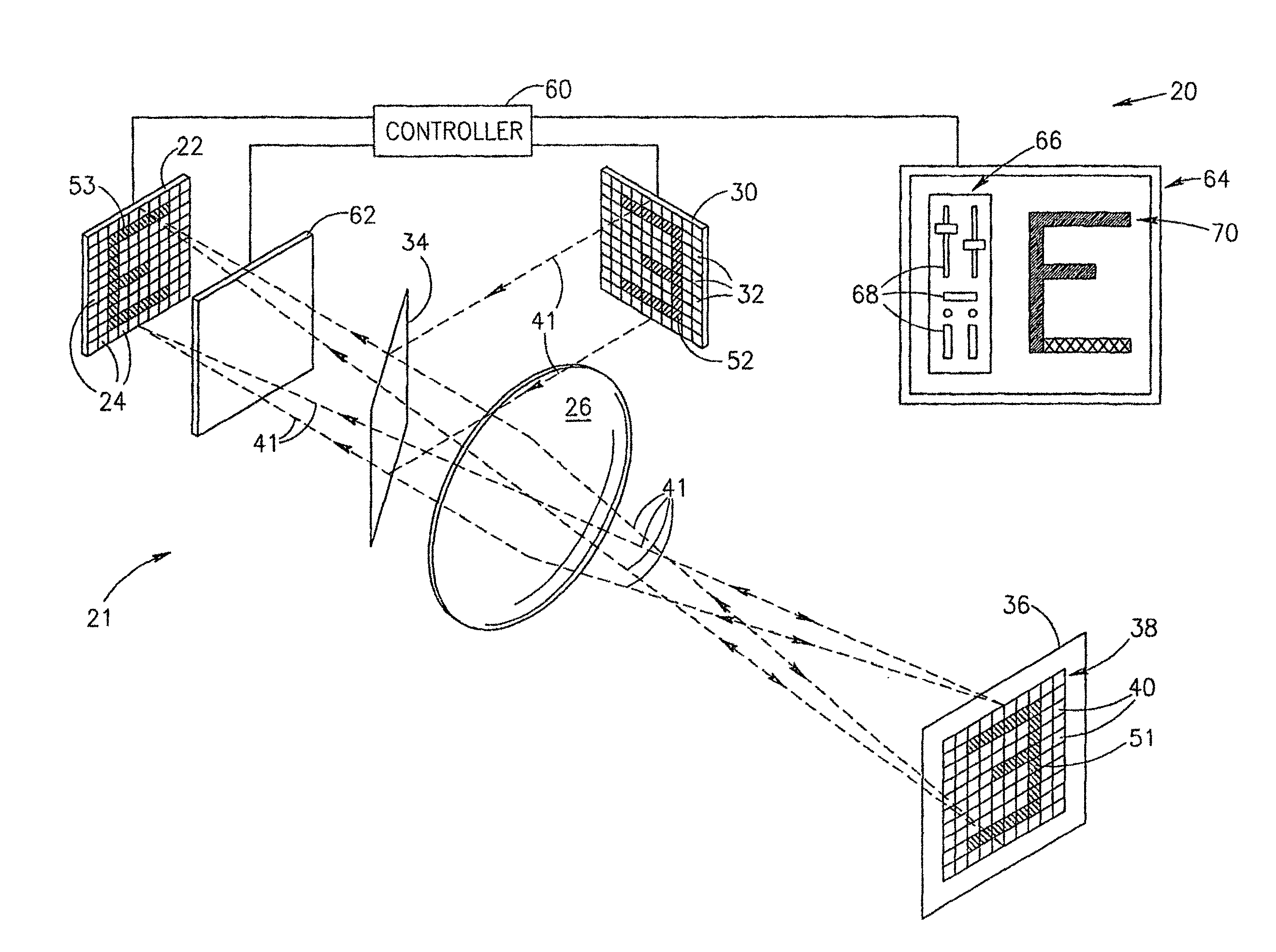
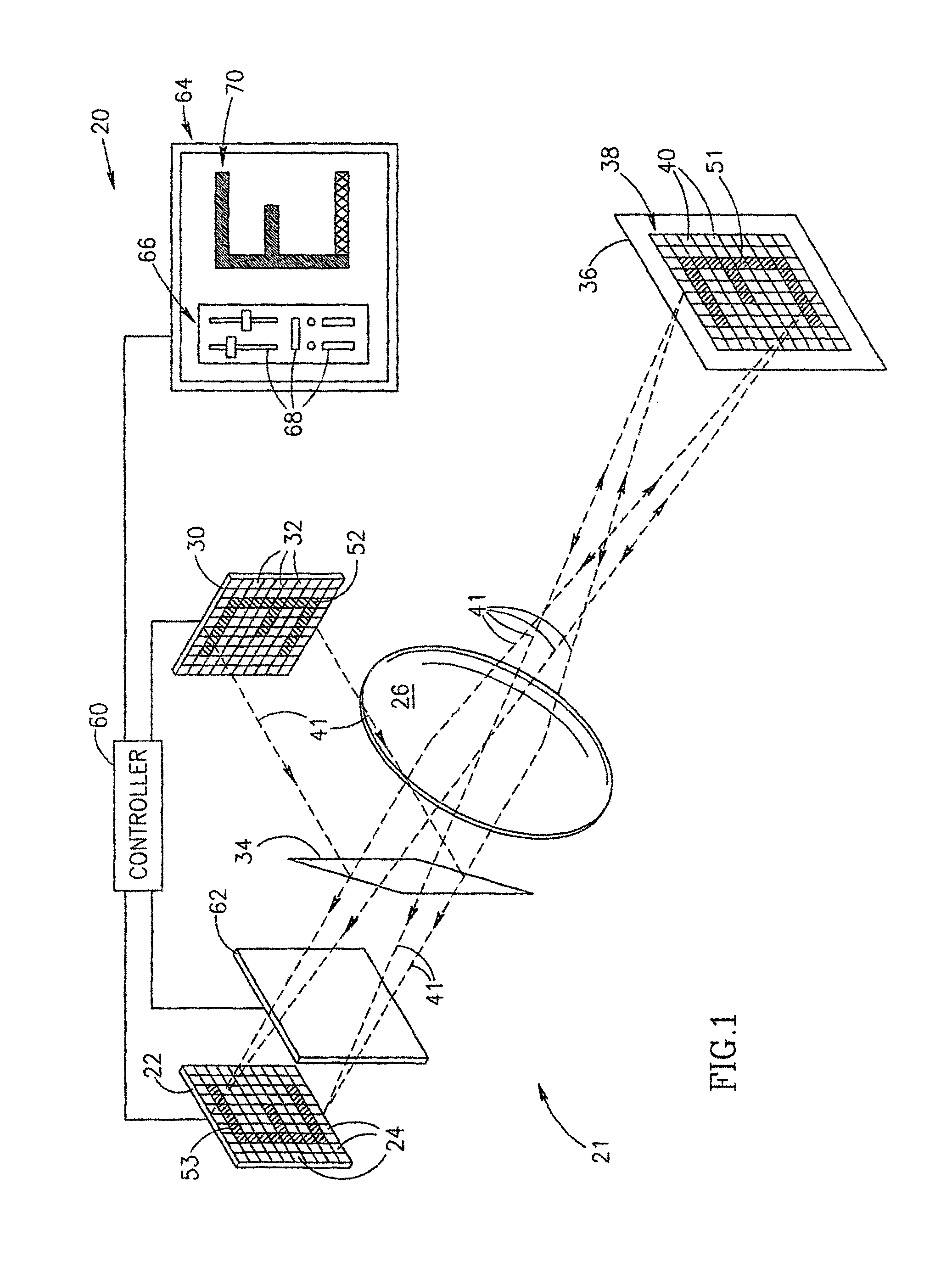
[0076]FIG. 1 schematically shows a camera 20 comprising an illumination system 21, in accordance with an embodiment of the present invention.

[0077]Camera 20 comprises a photosurface 22, such as a CCD or CMOS light sensitive surface, having pixels 24 and optics represented by a lens 26 for focusing an image of a scene on photosurface 22. Whereas, in FIG. 1 (and in FIGS. 2 and 3 discussed below) a single lens 26 represents the optics, the optics may comprise any suitable optical system, which may have a plurality of lenses and optical elements, as known in the art, for focusing images on photosurface 22.

[0078]Illumination system 21 comprises a pixelated illuminator 30 having a plurality of light providing luxels 32. Pixelated illuminator 30 is boresighted with photosurface 22 using an appropriate beam splitter 34 and optical elements (not shown) as might be required, so that optimally, a virtual image of pixelated illuminator 30 is substantially coincident with photosurface 22. It is ...


PUM


Abstract

A camera comprising: a photosurface comprising light sensitive pixels that generate signals responsive to light incident thereon and optics that focus an image of a scene onto the photosurface; and an illumination system for illuminating the scene, the illumination system comprising: an illuminator having a plurality of substantially contiguous, independently controllable light providing regions; optics that focuses an image or the illuminator on the scene so that light from the illuminator illuminates substantially all of and substantially only the field of view of the camera; and a controller that controls light provided by each light providing region.

Description

RELATED APPLICATIONS[0001]The present application is a US national application of PCT Application No. PCT / IL00 / 00404, filed on Jul. 9, 2000. This application is also a continuation-in-part of U.S. application Ser. No. 09 / 250,322, filed on Feb. 16, 1999, now U.S. Pat. No. 6,445,884.FIELD OF THE INVENTION[0002]The present invention relates to imaging a scene with light and in particular to methods and apparatus for illuminating the imaged scene.BACKGROUND OF THE INVENTION[0003]Satisfactory and effective imaging of a scene with light requires proper illumination of the scene. In many instances however, achieving proper illumination is a relatively complicated and arduous task. Often it is desirable and / or necessary to illuminate different regions of a scene with different intensity and / or color light. Sometimes a dynamic range of a camera limits contrast in an image of a scene and brightest regions and dimmest regions of the scene cannot be properly imaged at the same time. Sometimes l...

Claims


Application Information

Patent Timeline
Patent Type & Authority Patents(United States)
IPC IPC(8): H04N5/222G03B15/02B60Q1/08B60Q1/52G01C11/02G01S7/48G01S7/481G01S7/51G01S15/89G01S17/08G01S17/18G01S17/88G01S17/89G02B7/32G02B27/00G03B1/00H04N5/225H04N5/235
CPCB60Q9/008F21S48/115F21S48/1747G01C11/025G01S17/08G01S17/89G02B7/32H04N5/2256H04N5/2354B60Q2400/50G01S7/4812G01S7/51G01S17/107G01S17/88F21S41/141F21S41/147F21S41/663G01S17/18H04N23/56H04N23/74
Inventor BRAUN, ORI J.YAHAV, GIORA
Owner MICROSOFT INT HLDG BV
Why Eureka
Try Eureka