
Apparatus and Method for Controlling Internal Test Controllers

Inactive Publication Date: 2015-02-12
APPLE INC
View PDF12 Cites 10 Cited by
  • Summary
  • Abstract
  • Description
  • Claims
  • Application Information

AI Technical Summary

Benefits of technology

The patent describes an apparatus and method for controlling two types of test controllers: JACK controllers and ECT controllers. The JACK controllers are able to operate according to a first protocol, and the ECT controllers are able to operate according to a second protocol. The ECT controllers can control their respective JACK controllers in parallel and independently of each other. A partition selection register is implemented to activate the JACK controller by setting a bit in a corresponding ECT storage location. This allows for efficient control of the JACK controller in an automated testing system.

Problems solved by technology

Any number of JTAG controllers may be coupled to one another in series, and thus they may be used in large, complex IC designs.

Method used


Image

  • Apparatus and Method for Controlling Internal Test Controllers
  • Apparatus and Method for Controlling Internal Test Controllers
  • Apparatus and Method for Controlling Internal Test Controllers

Examples


Embodiment Construction

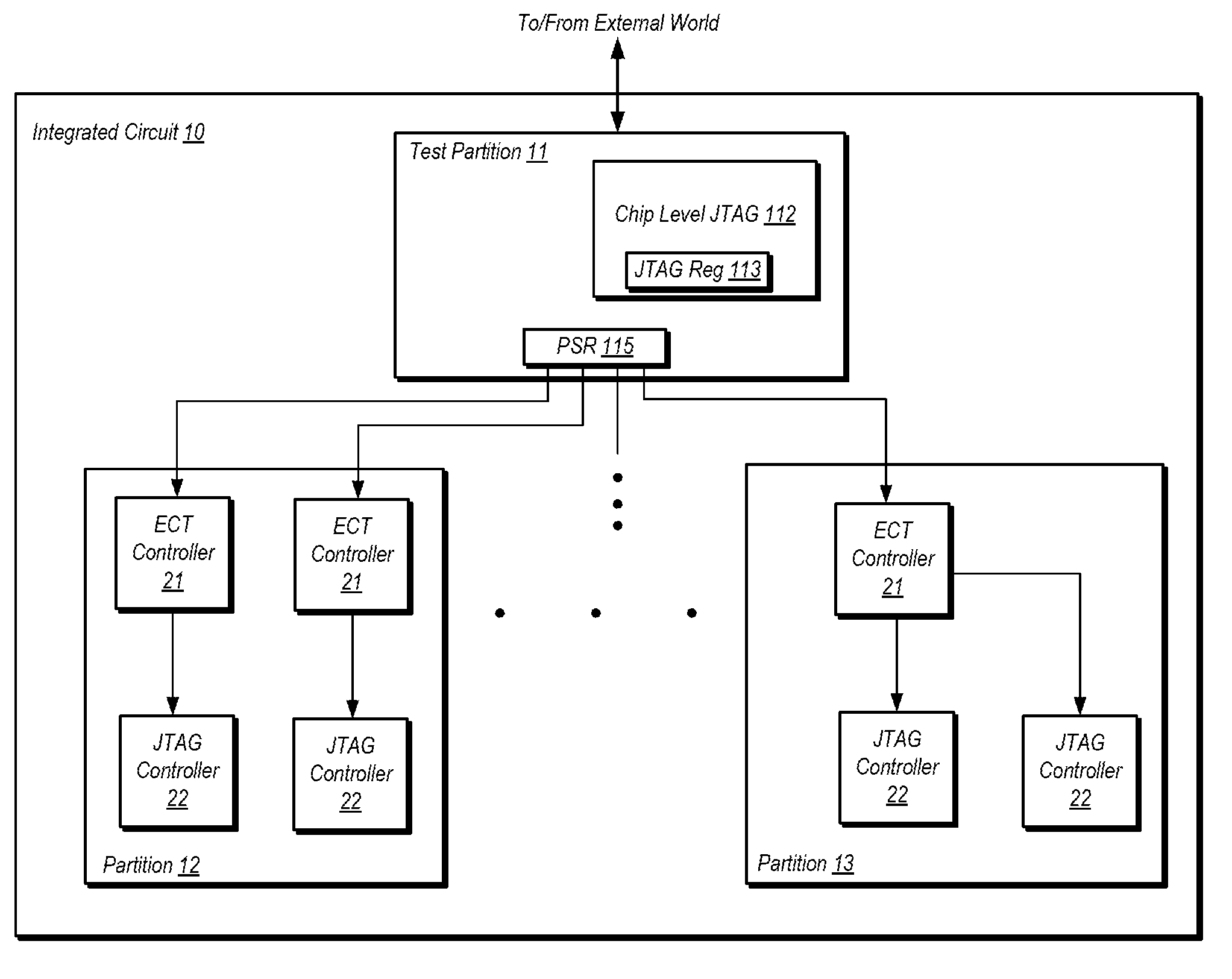
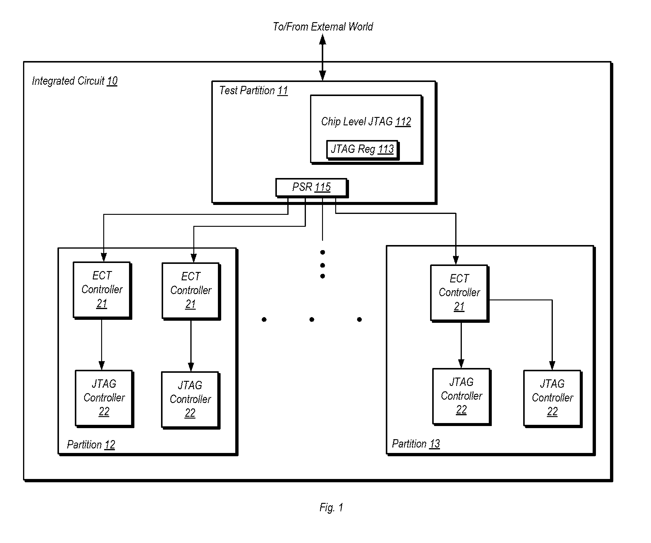
[0017]Turning now to FIG. 1, a block diagram of one embodiment of an integrated circuit (IC) is shown. It is noted that FIG. 1 is a simplified block diagram that does not show many elements of a typical IC, such as the functional units that perform the various operations therein. The block diagram shown here is simplified to more clearly illustrate the particular functionality disclosed herein and discussed in further detail below.

[0018]In the embodiment shown, IC 10 includes a number of different partitions, including partition 11, partition 12, and partition 13. A partition may be defined herein in various ways. For example, a partition may be defined as a group of related circuits, such as those circuits of a particular functional units or circuits that are generally related by function. A partition may also be defined by the circuits that are included in a particular power domain and / or clock domain. In general, a partition may be defined by circuits that are related by at least...


PUM


Abstract

An apparatus and method for controlling a test controller is disclosed. An apparatus includes test controllers of a first type configured to operate according to a first protocol and test controllers of a second type configured to operate according to a second protocol. A test controller of the second type may be associated with one of the test controllers of the first type, with the former controlling the latter. The test controllers of the second type may each control associated ones of the test controllers of the second type in parallel and independently of one another.

Description

BACKGROUND[0001]1. Technical Field[0002]This disclosure is directed to integrated circuits, and more particularly, to the access of test interfaces for integrated circuits.[0003]2. Description of the Related Art[0004]Boundary scan testing was originally developed to test connections between integrated circuits (IC's) and printed circuit boards (PCB's) in the absence of other ways to probe them. Boundary scan is based on the Joint Test Action Group (JTAG) specification, which is also known at the Institute of Electrical and Electronic Engineers (IEEE) Standard 1149.1. In particular, the IEEE 1149.1 standard provided a mechanism for providing access to pins of an IC to determine the presence of proper connections.[0005]Although the IEEE 1149.1 standard was originally developed for boundary scan, its uses have expanded to other areas. For example, JTAG ports are now used to obtain access to an IC for debugging during the development phase. For example, a JTAG controller may be used to ...

Claims


Application Information

Patent Timeline
Patent Type & Authority Applications(United States)
IPC IPC(8): G01R31/3177
CPCG01R31/3177G01R31/318555
Inventor MAKAR, SAMY R.YU, JIANLINRAMASWAMI, RAVI K.
Owner APPLE INC
Learn More