Burner cup

a technology of burners and burners, which is applied in the direction of candle wicks, light and heating equipment, candle wicks, etc., can solve the problems of inability to control satisfactorily, inconvenient use, and inability to meet the needs of use,

Active Publication Date: 2015-02-19
LAMPLIGHT FARMS
View PDF8 Cites 8 Cited by
  • Summary
  • Abstract
  • Description
  • Claims
  • Application Information

AI Technical Summary

Problems solved by technology

Especially when used outdoors, regular fiber-wicked candles may suffer from inadvertent extinguishment owing to the low quantity of fuel they burn per wick.
Larger wicks can produce more robust flames but these can be difficult to control satisfactorily and are often sooty or smoky...

Method used


Image

  • Burner cup
  • Burner cup
  • Burner cup

Examples


Embodiment Construction

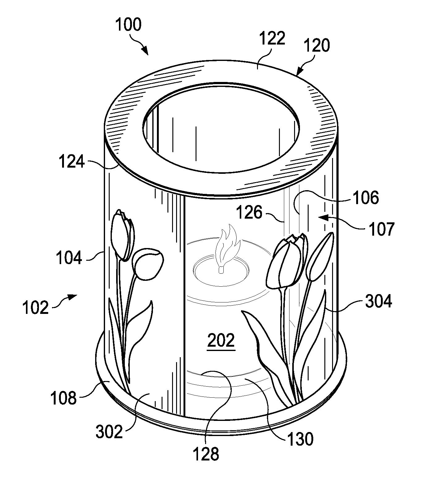
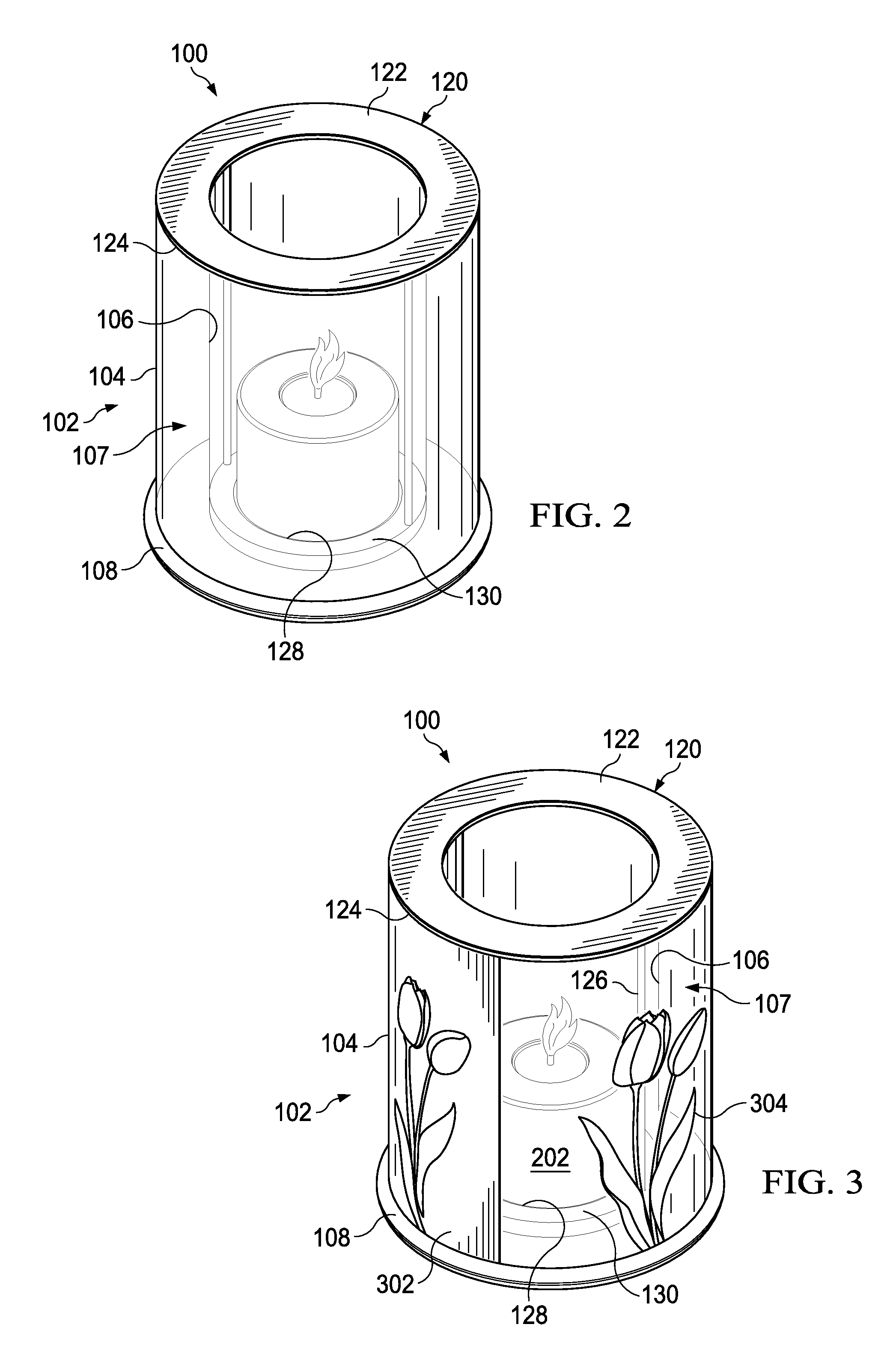
[0028]Referring now to FIG. 1, a perspective view of a light holder according to aspects of the present disclosure is shown. For purposes of the present disclosure, the term light holder is understood to mean a device that may contain a fuel burning device or other light producing device therein. For example, the light holder 100 may contain various burner cups as described below.

[0029]The light holder 100 comprises a container 102. In the present embodiment, the container 102 comprises an outer wall 104 and an inner wall 106. A space 107 is defined between the outer wall 104 and the inner wall 106. In some embodiments, this space 107 will serve as an insulating barrier and, in other embodiments, may be used for decorative purposes, as will be described further below. In the present embodiment, the outer wall 104 and the inner wall 106 connect to the base 108.

[0030]In some embodiments, the outer and inner wall 104, 106, will be formed from separate pieces and attached to the base 10...


PUM


Abstract

A device has a canister with a bulk wick occupying at least most of the canister, and a lid affixed to the canister and in contact with the bulk wick. The lid defines an opening exposing a portion of the bulk wick for lighting.

Description

CROSS REFERENCE TO RELATED APPLICATIONS[0001]This application claims the priority of U.S. Provisional Patent Application No. 61 / 867,415, titled “BURNER CUP,” filed Aug. 19, 2013, and U.S. Provisional Patent Application No. 61 / 887,120, titled, “ILLUMINATION SOURCE,” filed Oct. 4, 2013, and U.S. Provisional Patent Application No. 62 / 018,344, titled “SOLID LID BURNER CUP,” filed Jun. 27, 2014, the contents of each of which are hereby incorporated by reference.FIELD OF THE INVENTION[0002]This disclosure relates to the field of fuel burning lamps and burners in general and, more specifically, to products capable of providing enhanced flame effects utilizing low flammability fuel.BACKGROUND OF THE INVENTION[0003]Candles, lamps, and lanterns have been used for lighting since ancient times. Although modern households rely on electric lighting, the use of these combustion-based devices has never completely subsided. Combusting light implements are used even in modern times as a backup or eme...

Claims


Application Information

Patent Timeline
IPC IPC(8): C11C5/00F21V35/00
CPCF21V35/00C11C5/006C11C5/00C11C5/008F21V37/002
Inventor KIMMEL, ADAM S.WHITE, RONCATALANO, RICHARD
Owner LAMPLIGHT FARMS
Why Eureka
Try Eureka