Moving window installation structure of sliding window system having aluminum alloy sash structure

a technology of sliding window system and installation structure, which is applied in the direction of door/window fittings, wing accessories, wing arrangements, etc., can solve the problems of not providing a high sealing effect, unable to expect an excellent performance in connection with a soundproof property, airtight property, heat insulation property, etc., and achieves enhanced wind pressure resistance against wind pressure, improved heat insulation function, and reduced dew condensation phenomenon.

Active Publication Date: 2015-02-26
FILOBE
View PDF12 Cites 21 Cited by
  • Summary
  • Abstract
  • Description
  • Claims
  • Application Information

AI Technical Summary

Benefits of technology

[0053]According to the present invention it is possible to provide an installation structure of a sliding window system which enables sealing and unsealing of a sliding window in which a profile cross-section structure of a window installation frame provided with a sliding window of an aluminum alloy sash structure is improved such that a heat insulation function can be remarkably improved, a dew condensation phenomenon can be minimized, and a wind pressure resistance against wind pressure can be enhanced. It is also possible to provide an open / close structure of a sliding window in which the moving window can be smoothly slid for sealing in a direction orthogonal to the longitudinal direction of a rail while preventing a vertical reaction force from being applied between the rail and the roller device.
[0054]In addition, according to the present invention, the moving window can be smoothly slid while the moving window is moved in a substantially vertical direction regardless of the magnitude of the weight of the moving window so that a complete sealing action can be smoothly implemented.

Problems solved by technology

However, with such a conventional and simple configuration, it is usually difficult to expect an excellent performance in connection with a soundproof property, an airtight property (windbreak property), a watertight property, a heat insulation property, a wind pressure resistance property, or the like.
However, due to the limitation in a sealing method, the sealing member, such as the windbreak hair or the windbreak rubber, does not provide a high sealing effect.
Furthermore, since the sealing member is deformed or worn out as time goes on, it is difficult to maintain the performance constantly.
However, the “LS” type open / close structure as described above has problems as follows.
The sliding frame having heavy-weighted components related to the roller installed at the lower portion of the moving window should be moved up or down in order to open or close the moving window, which is mechanically disadvantageous due to concentrated loads applied to the roller portion, and an apparatus that should frequently conduct the functions of moving the moving window up and down as described above requires endurable high-performance components.
In addition, when the size of the sliding frame exceeds a certain range, it may be difficult to overcome the burden of the weights of the enlarged sliding frame and glass window.
Thus, there is a problem in that an applicable size of the sliding frame is limited.
Thus, it is not easy to secure a complete sealing performance at corner portions of the sliding frame and the window frame where the different sealing methods meet.
Further, it is difficult to achieve a complete sealing at the top side of the sliding frame since the sealing performance at the top side should be secured only by a small force that causes the upper sealing member 3u to be elastically in close contact with the upper guide rail 1a.
In particular, it is also difficult to block the heat transfer through the upper guide between the inside and outside areas.
Furthermore, in view of the state in which the roller 4r is installed within the inner frame 4a of the lower frame of the moving window 4, it is unavoidable to arrange the thermal break 4c adjacent to the roller 4r.
However, this is rather disadvantageous in providing support rigidity because the frame supporting the roller 4r is cut.
Thus, it is difficult to provide a separate rigid frame capable of improving the longitudinal rigidity of the entire frame of the moving window 4.
Thus, there is a problem in that when the window is enlarged, there is no means that may provide sufficient endurance against wind pressure.
Consequently, the reaction force also may act as a large frictional force between the roller and the rail and may disturb the movement of the roller which is to be traveled along the rail by the horizontal component force Fh.

Method used


Image

  • Moving window installation structure of sliding window system having aluminum alloy sash structure
  • Moving window installation structure of sliding window system having aluminum alloy sash structure
  • Moving window installation structure of sliding window system having aluminum alloy sash structure

Examples


Embodiment Construction

Technical Problem

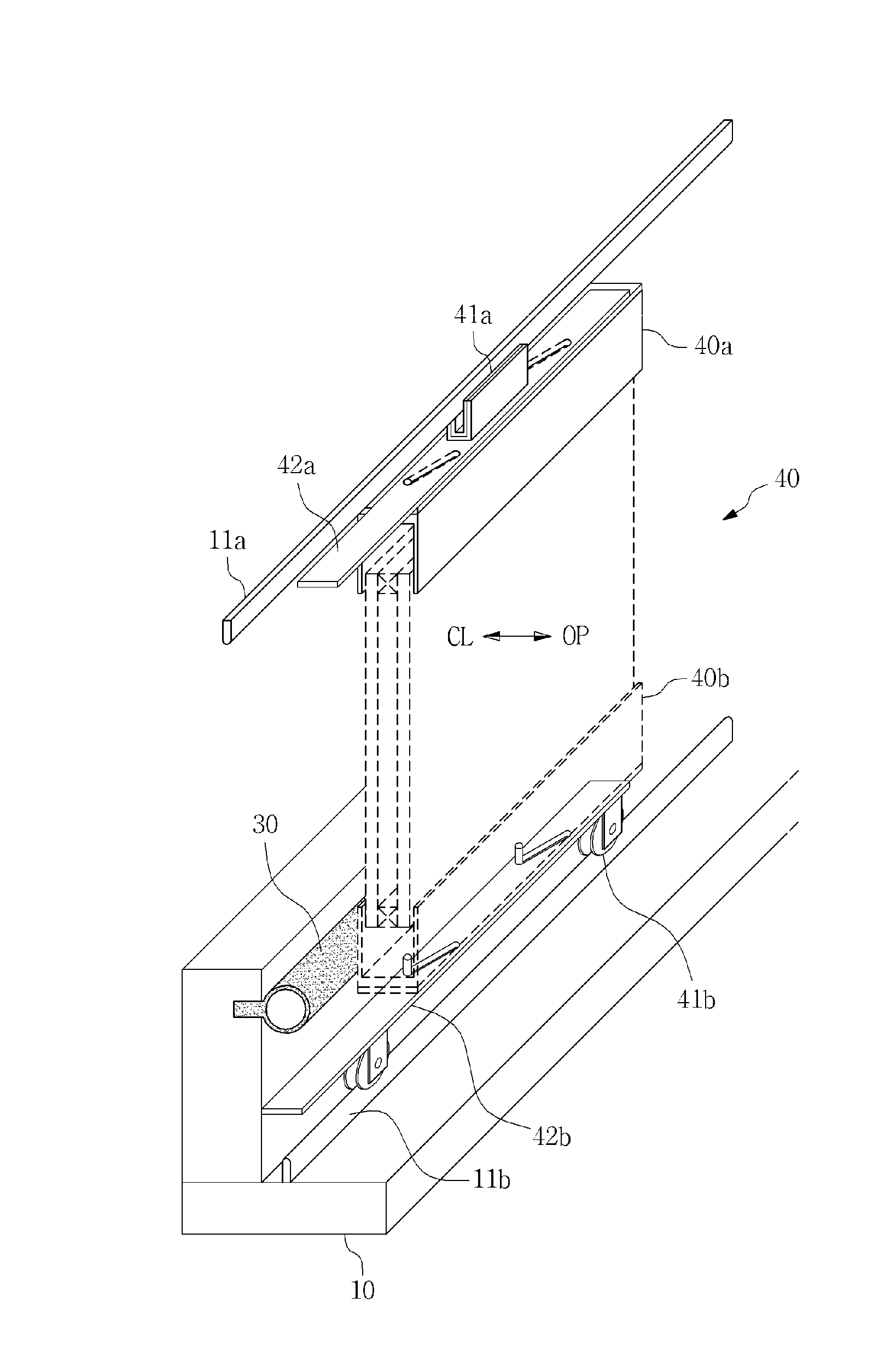
[0022]The present invention has been made in an effort to solve the problems as described above and a technical object of the present invention is to provide a moving window installation structure of a sliding window system which is configured to improve a profile cross-section structure of a window installation frame provided with a sliding window such that heat insulation can be remarkably improved and wind pressure resistance against wind pressure can be enhanced, and to provide a sliding window structure which is configured to prevent a vertical reaction force from being applied between a rail and a roller for supporting the weight of a moving window that constitutes a sliding window having an aluminum alloy sash structure such that the moving window can be smoothly moved in a direction perpendicular to the longitudinal direction of the rail.

[0023]Another technical object of the present invention is to provide a sliding window structure which is configured such ...


PUM

PropertyMeasurementUnit
lengthaaaaaaaaaa
angleaaaaaaaaaa
forceaaaaaaaaaa

Abstract

The present invention relates to a moving window installation structure of a sliding window system. More specifically, the present invention relates to a moving window installation structure of a sliding window system which is configured to prevent a vertical reaction force from being applied between a rail and a roller for supporting the weight of a moving window that constitutes a sliding window having an aluminum alloy sash structure such that the moving window can be smoothly moved in a direction perpendicular to the longitudinal direction of the rail and the sliding mobility of a large-sized window having a heavy weight can be improved, and to improve a profile cross-section structure of a window installation frame provided with a sliding window such that heat insulation can be remarkably improved and wind pressure resistance against wind pressure can be enhanced.

Description

TECHNICAL FIELD[0001]The present invention relates to a moving window installation structure of a sliding window system and, more specifically, to a moving window installation structure of a sliding window system which is configured to prevent a vertical reaction force from being applied between a rail and a roller for supporting the weight of a moving window that constitutes a sliding window having an aluminum alloy sash structure such that the moving window can be smoothly moved in a direction perpendicular to the longitudinal direction of the rail and the sliding mobility of a large-sized window having a heavy weight can be improved, and to improve a profile cross-section structure of a window installation frame provided with a sliding window such that heat insulation can be remarkably improved and wind pressure resistance against wind pressure can be enhanced.BACKGROUND ART[0002]Referring to a most conventional configuration of a sliding frame (within which a panel such as a gla...

Claims


Application Information

Patent Timeline
Patent Type & Authority Applications(United States)
IPC IPC(8): E05D15/06E06B3/46E06B7/16E05D13/00
CPCE05D15/0621E05D13/12E05D15/0665E06B7/16E06B3/4609E05D15/1013E05Y2900/148E06B3/4627E06B7/2307E06B3/263E06B5/20E05D15/10
Inventor LEE, KWANG-SEOK
Owner FILOBE
Why Eureka
Try Eureka