Load Supporting Apparatus

a technology for supporting apparatus and load, which is applied in the direction of mechanical apparatus, machine supports, other domestic objects, etc., can solve the problems of not being able to adapt the support device to the height of the user, the use of this conventional support device is not without any problems, and the adjustment is impossible without any device, so as to achieve the effect of supporting apparatus

Inactive Publication Date: 2015-02-26
CONTINEW INCORPRATION
View PDF2 Cites 26 Cited by
  • Summary
  • Abstract
  • Description
  • Claims
  • Application Information

AI Technical Summary

Benefits of technology

[0007]It is the primary objective of the present in...

Problems solved by technology

The use of this conventional support device is however not without any problem.
At first, the support device is not ad...

Method used


Image

  • Load Supporting Apparatus
  • Load Supporting Apparatus
  • Load Supporting Apparatus

Examples


Embodiment Construction

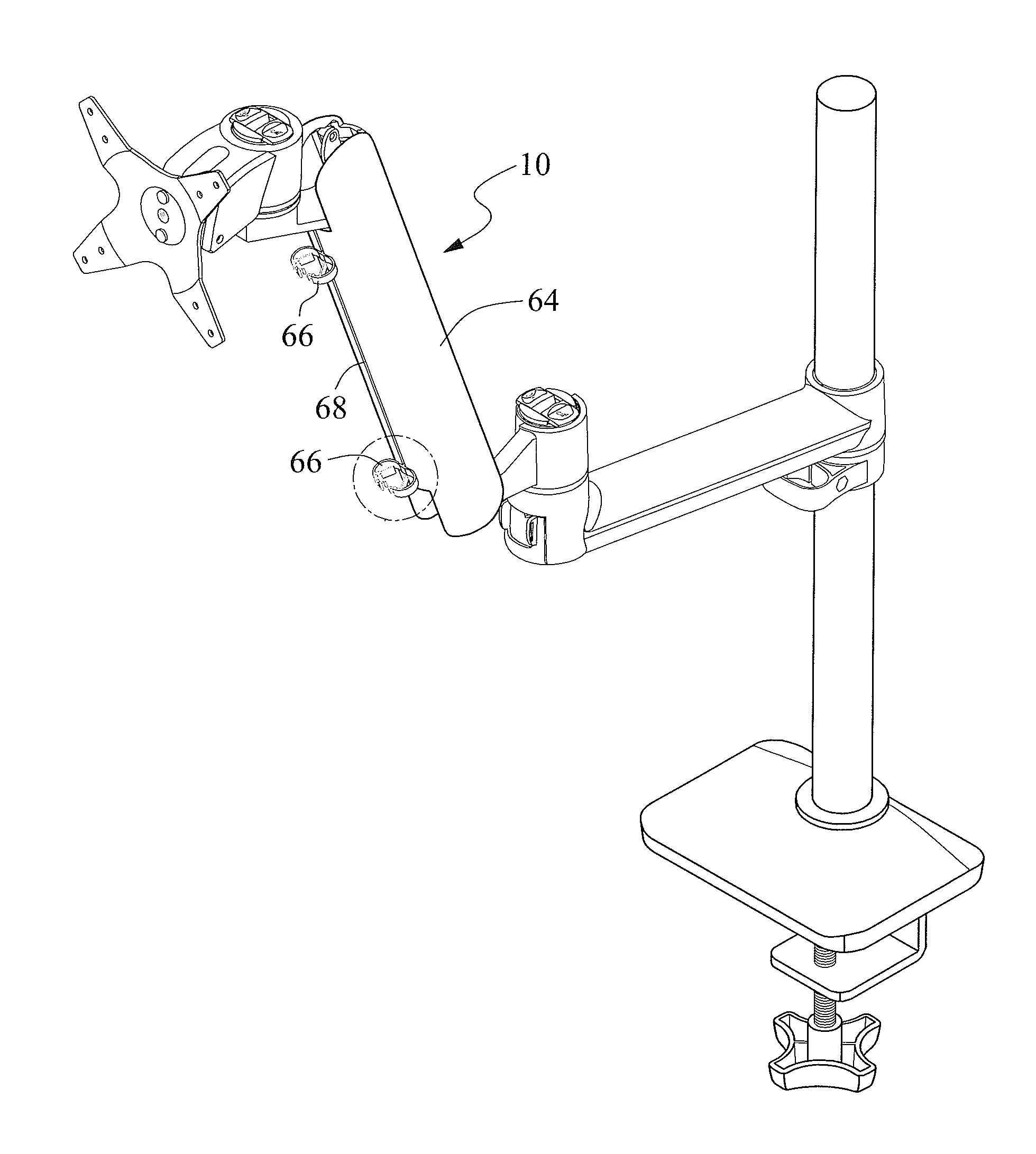
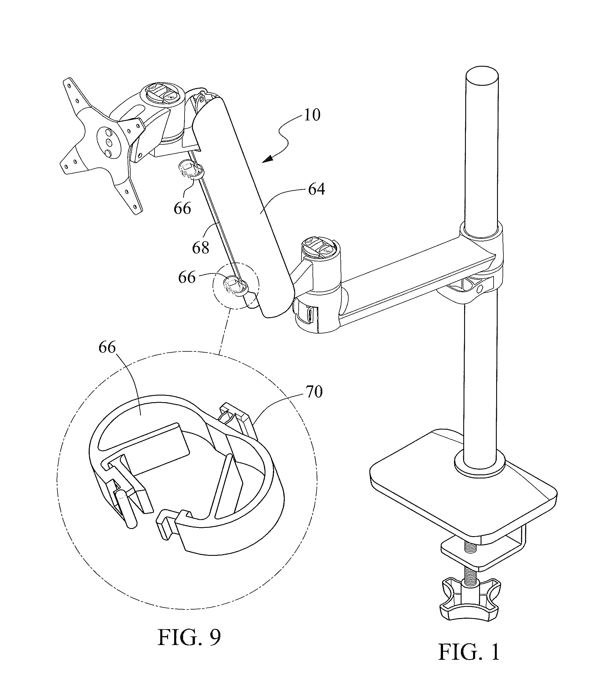
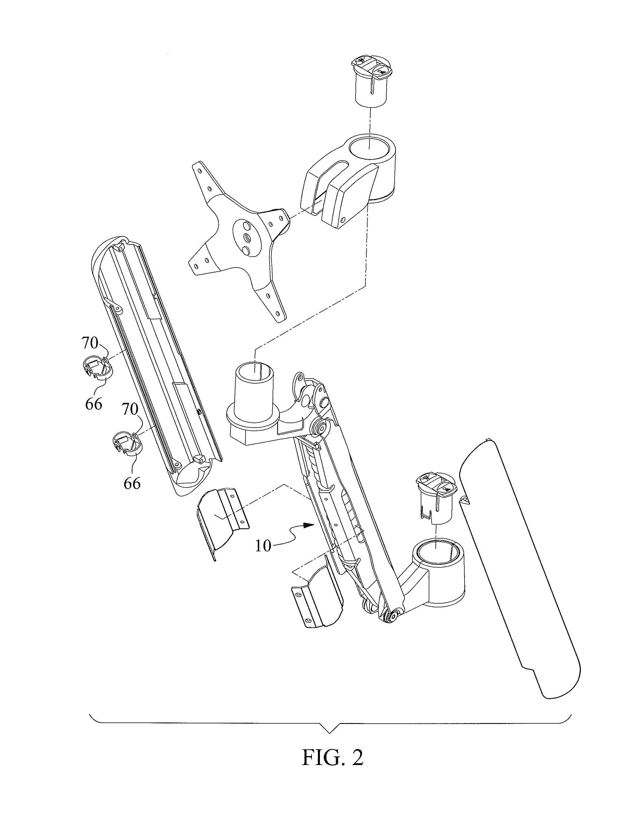
[0020]Referring to FIGS. 1 to 5, a load-supporting apparatus 10 includes a four-bar linkage according to the preferred embodiment of the present invention. The four-bar linkage includes levers 12, 14, 16 and 18. Each of levers 12, 14 and 16 includes a middle portion extending between two parallel fins. Accordingly, there are two identical levers 18. Each lever 18 is a flat element. Load-supporting apparatus 10 further includes a pushing element 20, two hanging elements 22 and an extending device 24. Pushing element 20 includes a middle portion extending between two parallel fins. Each hanging element 22 is a flat element.

[0021]Lever 12 is formed with first and second ends. There is a rivet 32 for connecting the second end of lever 12 to a first end of lever 14. There is a rivet 34 for connecting a second end of lever 14 to a first end of lever 16. There is a rivet 36 for connecting a second end of each fin of lever 16 to a first end of a corresponding lever 18. There is a rivet 38 f...


PUM


Abstract

A load-supporting apparatus includes four levers each including first and second ends, a pushing element, a hanging element and an extending device. The first end of the second lever is connected to the second end of the first lever. The first end of the third lever is connected to the second end of the second lever. The first end of the fourth lever is connected to the second end of the third lever. The second end of the fourth lever is connected to the first end of the first lever. A first end of the pushing element is connected to the first lever. A first end of the hanging element is connected to a second end of the pushing element. A first end of the extending device is connected to the first end of the hanging element. The second end of the extending device is placed against the second lever.

Description

BACKGROUND OF INVENTION[0001]1. Field of Invention[0002]The present invention relates to a load-supporting apparatus and, more particularly, to a linkage for supporting a load.[0003]2. Related Prior Art[0004]As disclosed in U.S. Pat. No. 6,478,275, a conventional support device includes a base 10, a bracket 20, an arm 30, a lever 40 and a spring 50. The bracket 20 is used to carry an object. The arm 30 is pivotally secured to the base 10 with a shaft 31. The lever 40 is secured to the base 10 with a rod 42. The lever 40 includes a curved groove 43 for slidably receiving the shaft 31 and an orifice 41 for loosely receiving the rod 42. The base 10 includes a stop 11 for engaging and latching the lever 40 with the base 10, without additional fasteners, when the lever 40 is elevated relative to the base 10. The spring 50 includes an end placed against the rod 42 and another end placed against the arm 30 so that the spring 50 tends to keep the arm 30 in a vertical position when the base ...

Claims


Application Information

Patent Timeline
IPC IPC(8): F16M13/02F16M11/06
CPCF16M13/022F16M11/06F16M11/12F16M11/04D06F75/28F16G13/16F16M11/2014F16M11/2092F16M11/24F16M2200/044F16M2200/063F16M2200/065Y10S248/917
Inventor LU, CHIN CHANG
Owner CONTINEW INCORPRATION
Why Eureka
Try Eureka