Eureka AIR delivers breakthrough ideas for toughest innovation challenges, trusted by R&D personnel around the world.

Method of correcting image-overlapped area, recording medium and execution device

Active Publication Date: 2015-02-26
CJ 4DPLEX CO LTD
View PDF14 Cites 3 Cited by
  • Summary
  • Abstract
  • Description
  • Claims
  • Application Information

AI Technical Summary

Benefits of technology

The invention allows multiple projectors to show an image that has a sense of unity and harmony. By controlling the factors of the images in the overlapping areas, the difference between them can be minimized.

Problems solved by technology

However, the audience has no choice but to watch only the two-dimensional (2D) image in such a system.
However, although the 3D techniques may provide images having a sense of depth to users, there is a limit in that it is difficult to be absorbed in the image itself since it is merely watching an image played back on a single screen.
In addition, there is also a limit in that the direction of the sense of depth felt by the audience is restricted to the direction where the single screen exists.
In addition, since the conventional 3D techniques require the audience to wear glasses or the like having polarized light filters when watching an image, it is inconvenient for the audience who watch the image, and since different images are artificially and forcibly injected into the left and right eyes, sensitive audience may feel dizzy or nausea.
It is since that in the ‘multi-projection system’, a plurality of images projected on a plurality of projection surfaces, not on a single projection surface, should be integratedly corrected, and the method of correcting a plurality of images should be changed as the structure of a theater changes, and, therefore, an image correction process is very complicated, and an error is highly probable to occur.

Method used


Image

  • Method of correcting image-overlapped area, recording medium and execution device
  • Method of correcting image-overlapped area, recording medium and execution device
  • Method of correcting image-overlapped area, recording medium and execution device

Examples


Embodiment Construction

[0028]Hereinafter, the present invention will be described in detail with reference to the accompanying drawings.

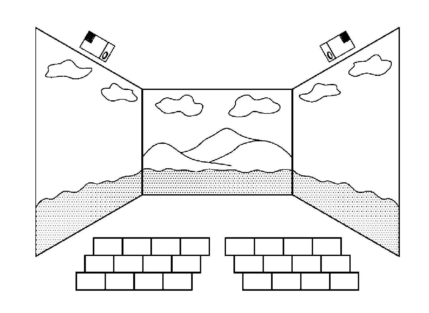
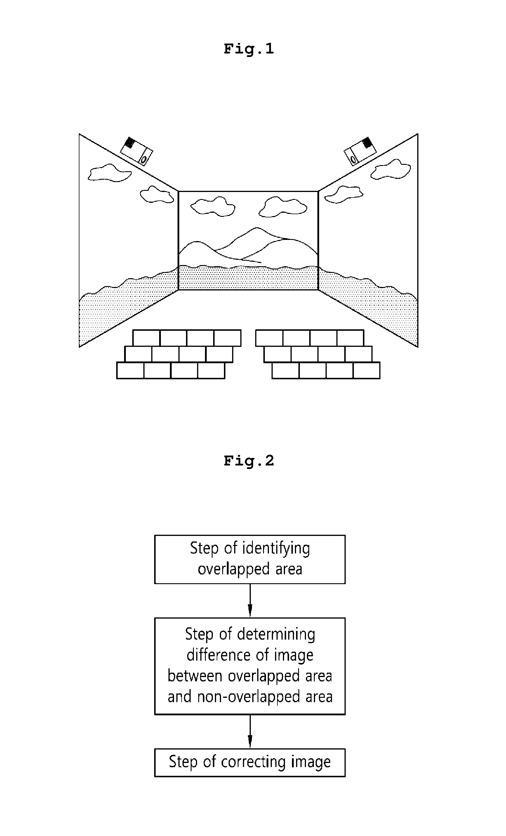
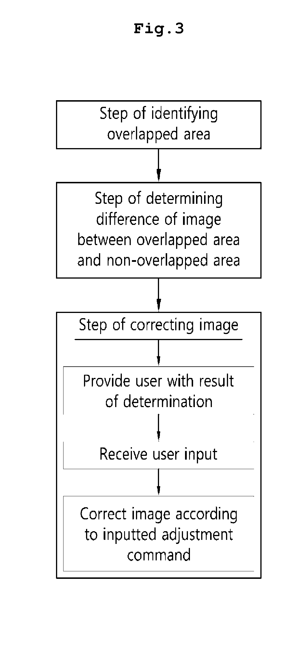
[0029]FIG. 2 is a flowchart illustrating an embodiment of the present invention. An image-overlapped area correction method of the present invention includes the steps of: identifying an overlapped area between images projected by a plurality of projectors, determining a difference of at least brightness or color of the overlapped area or a non-overlapped area, and adjusting a factor among the brightness and the color in which the difference is generated.

[0030]In order to identify an overlapped area between images, a point of a projection surface on which an image projected by each projector is projected should be confirmed first. To this end, in an embodiment of the present invention, each projector projects a reference image in which a predetermined pattern (e.g., a lattice pattern) is formed, and a point of the projection surface on which the reference image is project...


PUM


Abstract

The present invention relates to an image correction method, and more specifically, to a method of correcting an image-overlapped area, the method including the steps of: identifying an overlapped area in an image projected by a plurality of projectors; determining a difference of at least any one of brightness and color of the overlapped area and a non-overlapped area of the image; and adjusting a factor among the brightness and the color in which the difference is generated.

Description

TECHNICAL FIELD[0001]The present invention relates to an image processing method, and more specifically, to an image correction method for providing an image having a sense of unification overall by correcting an overlapped area in the images projected by a plurality of projectors.BACKGROUND ART[0002]Conventionally, in order to play back an image such as a movie, advertisement or the like in a theater, a two-dimensional image is projected on a single screen placed on the front side of the theater. However, the audience has no choice but to watch only the two-dimensional (2D) image in such a system.[0003]Recently, techniques related to 3D images have been developed to provide images having a sense of depth to the audience, and the 3D image techniques use a principle of feeling a sense of depth even from a planar image if different images respectively enter left and right eyes of a person and merge together in the brain, in which two cameras having different polarized light filters ar...

Claims


Application Information

Patent Timeline
IPC IPC(8): G09G5/02G03B37/04
CPCG09G5/02G03B37/04G09G2320/0666G09G2360/04G09G2340/12G09G2354/00G09G2320/0686G06F3/1446G09G3/003G09G5/026G09G2320/0693H04N9/3147H04N9/3182H04N9/31H04N9/64
Inventor KIM, HWAN CHULKANG, SU RYEONKANG, JI HYUNG
Owner CJ 4DPLEX CO LTD
Why Eureka
Eureka Blog
Learn More