
Progressive ophthalmic lens

Active Publication Date: 2021-02-04
HORIZONS OPTICAL S L U
View PDF0 Cites 0 Cited by
  • Summary
  • Abstract
  • Description
  • Claims
  • Application Information

AI Technical Summary

Benefits of technology

The present invention provides an ophthalmic lens that optimizes vision quality by evaluating physiological data from different parts of the eye and incorporating that data into the lens design. This new approach overcomes limitations of current progressive lenses.

Problems solved by technology

Presbyopia is a limited capacity of the accommodation power of the eye that increases with the age.
Despite lens designers try to obtain lenses with optimum optical quality in far vision area and near vision area by widening the field of view in these areas and lowering gradients of astigmatism in peripheric vision, progressive addition lenses in the market are not perfectly fulfilling the ideal targets because of the limitations established by Minkwitz.
Therefore, it is not a surprise that some wearers claim they do not feel comfortable with the quality of their progressive addition lenses, particularly in activities where near or intermediate vision zones are intensively used, like reading, or in computer activities, or more likely where peripheric vision or motion perception is required (driving, sports, etc.).
According to studies of non-adaptation of progressive lenses, some 5% to 8% of users do not adapt satisfactorily to progressive lenses (J. J Conejero in “Análisis de la adaptación de lentes progresivas para la corrección de la presbicia”, 2012) their main complaint is related to bad near and intermediate vision, particularly because of lateral distortions caused by the aberrations in the form of unwanted astigmatism, both its gradient and its absolute value.
While these occupational lenses can be optimized for either near, mid or far vision and achieve lower amounts of lateral astigmatism, they cannot be used for any vision activity because the addition profile along the progression path does not allow all-distance focusing.

Method used


Image

  • Progressive ophthalmic lens
  • Progressive ophthalmic lens
  • Progressive ophthalmic lens

Examples


example 1

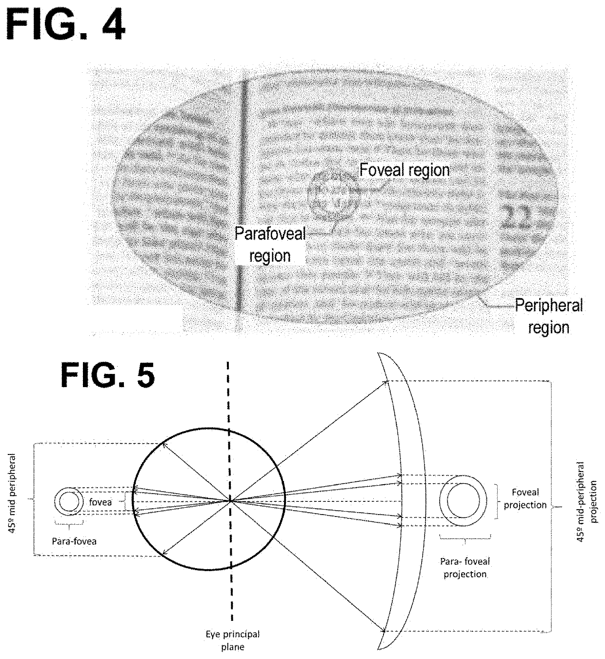
[0159]An optical lens element according to the present invention was designed having 2.00 D addition power in the lower or near viewing zone and standard corridor length (the near vision point situated 15 mm below the fitting cross). The contour plots of surface astigmatism and mean surface power respectively for the optical lens are given in FIGS. 8a and 8b. The design provides a relatively wide upper or distance viewing zone with the 0.5 D astigmatic contour rising towards the periphery. The lens design exhibits very low values of astigmatism along the lens progression path (0.4016 D for foveal projection and 0.5285 D for para-foveal projection). In addition, the maximum values of gradient of astigmatism along the progression path for foveal projection (0.269D) and para-foveal projection (0.275D) are obtained. We can see also that the maximum value of astigmatism and gradient of astigmatism for peripheral metric are below maximum values of table 2.

TABLE 3maximum values of the metr...

example 2

[0160]An optical lens element according to the present invention was designed having addition 2D and a short corridor length (the near vision point situated 12 mm below the fitting cross. Since this distance is not 15 mm, values of proposed maximum of astigmatism and maximum of gradient of astigmatism in the tables are recalculated to the current corridor length. For instance, foveal projection for the lens in this case, which has a corridor length of 12 mm leads to a maximum of astigmatism value of 0.5D:

(−0.03*12)+0.86D=0.50D,

which is always greater than the measured maximum of the lens according to the invention.

TABLE 5maximum values of the “Acuity” metricsfor the progressive lens of example 2.Maximum valueAcuity metric: Part ofMaximum valueof gradientthe retina that isof astigmatismof astigmatismprojected in thefor metricfor metricprogression path“Acuity” (D)“Acuity” (D / mm)Fovea0.431 (0.317Para-fovea0.61320.412

TABLE 6maximum values of the “Peripheral” metricsfor the progressive l...

example 3

[0162]An optical lens element according to the present invention was designed having of addition 2D with large corridor length, (the near vision point situated 18 mm below the fitting cross). FIGS. 10a and 10b shows the map of astigmatism and power of this lens.

[0163]Since this distance is not 15 mm, values of proposed maximum of astigmatism and maximum of gradient of astigmatism in the tables are recalculated to the current corridor length. For instance, foveal projection for the lens in this case, which has a corridor length of 18 mm leads to a maximum of astigmatism value of 0.35D instead of 0.41D:


PUM


Abstract

The progressive ophthalmic lens comprises at least one multifocal surface, in which at each point of its surface an astigmatism value and a gradient of astigmatism value can be measured, the lens comprising: a far-vision zone with a reference point (FV), a near-vision zone with a reference point (NV), an intermediate vision zone with a progression path that connects the far vision zone and the near vision zone, a foveal projection, and a para-foveal projection, and said lens defining a lens addition.If the lens addition is different than 2.00D, the astigmatism value is k*Add*0.41D, being Add the lens addition and k 0.5 and, if the progression path is shorter than 15 mm, the maximum astigmatism value of the foveal projection is substituted by (−0.03*d)D / mm+0.86D, if the lens progression path is larger than 15 mm, the maximum astigmatism value of the foveal projection is substituted by (−0.02*d)D / mm+0.71D.

Description

[0001]The present invention refers to a progressive ophthalmic lens that considers physiological data from retina.BACKGROUND OF THE INVENTION[0002]Presbyopia is a limited capacity of the accommodation power of the eye that increases with the age. Therefore, lenses with different optical power for far, intermediate, and near vision are usually proposed to correct presbyopia.[0003]Progressive ophthalmic lenses (PAL) are lenses that have an upper zone with optical correction for distance vision, a lower zone with correction for near vision, and an intermediate zone with a gradually varying optical power, known as progression path or corridor.[0004]The near-vision zone has a more positive optical power than the far-vision zone, and the difference in power between the far and near vision correction is known as addition. In general, the design of these lenses is intended to make the transition between far and near optical power as smooth as possible.[0005]According to a mathematical limit...

Claims


Application Information

Patent Timeline
IPC IPC(8): G02C7/06
CPCG02C7/066G02C7/063G02C7/065G02C7/027
Inventor COLOMER, PAU ARTUSPEÑALVER, GLORIA CASANELLASBLASCO, RAFAEL PERPIÑAN
Owner HORIZONS OPTICAL S L U
Learn More