Display device

a display device and speaker technology, applied in the field of display devices, can solve the problems of increasing the manufacturing cost of display devices, changing the design of speaker mounting structures, etc., and achieve the effect of mounting easily and securely

Inactive Publication Date: 2015-02-26
FUNAI ELECTRIC CO LTD
View PDF2 Cites 3 Cited by
  • Summary
  • Abstract
  • Description
  • Claims
  • Application Information

AI Technical Summary

Benefits of technology

[0015]In this preferred embodiment, the seal member is interposed between the speaker and the back casing and cover member, so the space between the speaker and the back casing and cover member is sealed. As a result, sound from the sound output unit is efficiently output outside the display device.
[0017]In this preferred embodiment, the speaker preferably is mounted on either the first mounting member or the second mounting member by inserting the protrusion into the indent, so the speaker is mounted easily and securely.

Problems solved by technology

However, the speaker mounting structure described above only works with a single size of speaker, which leads to the problem that when the size of the speaker is to be changed, the design of the speaker mounting structure must be changed for the new size of the speaker.
Furthermore, molds and the like for forming the casing must be changed when changing the design of the speaker mounting structure, which also creates the problem of increasing the manufacturing cost of the display device.

Method used


Image

  • Display device
  • Display device
  • Display device

Examples


first preferred embodiment

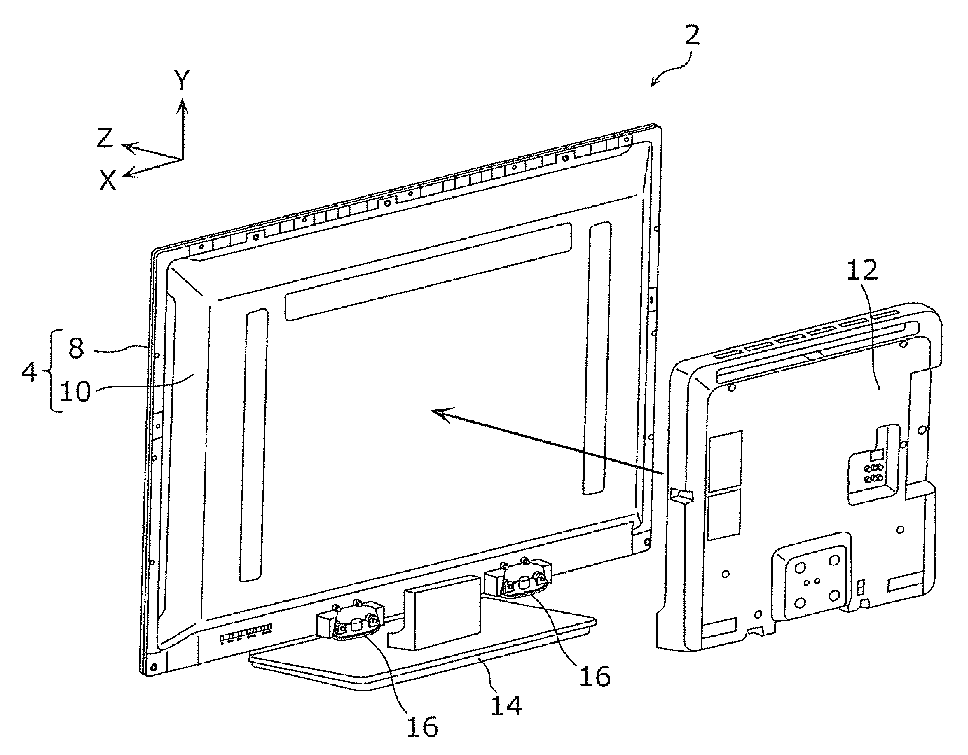
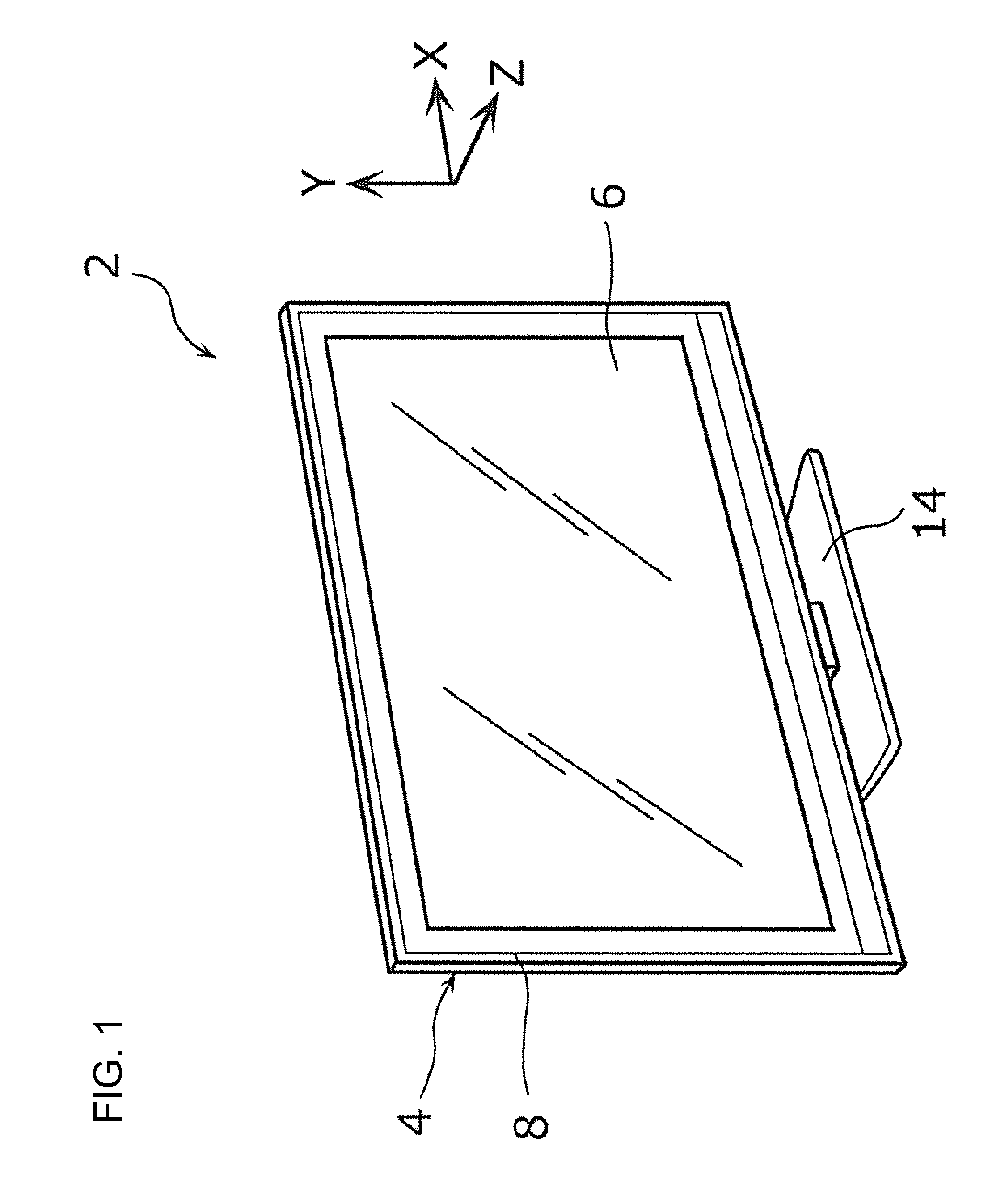
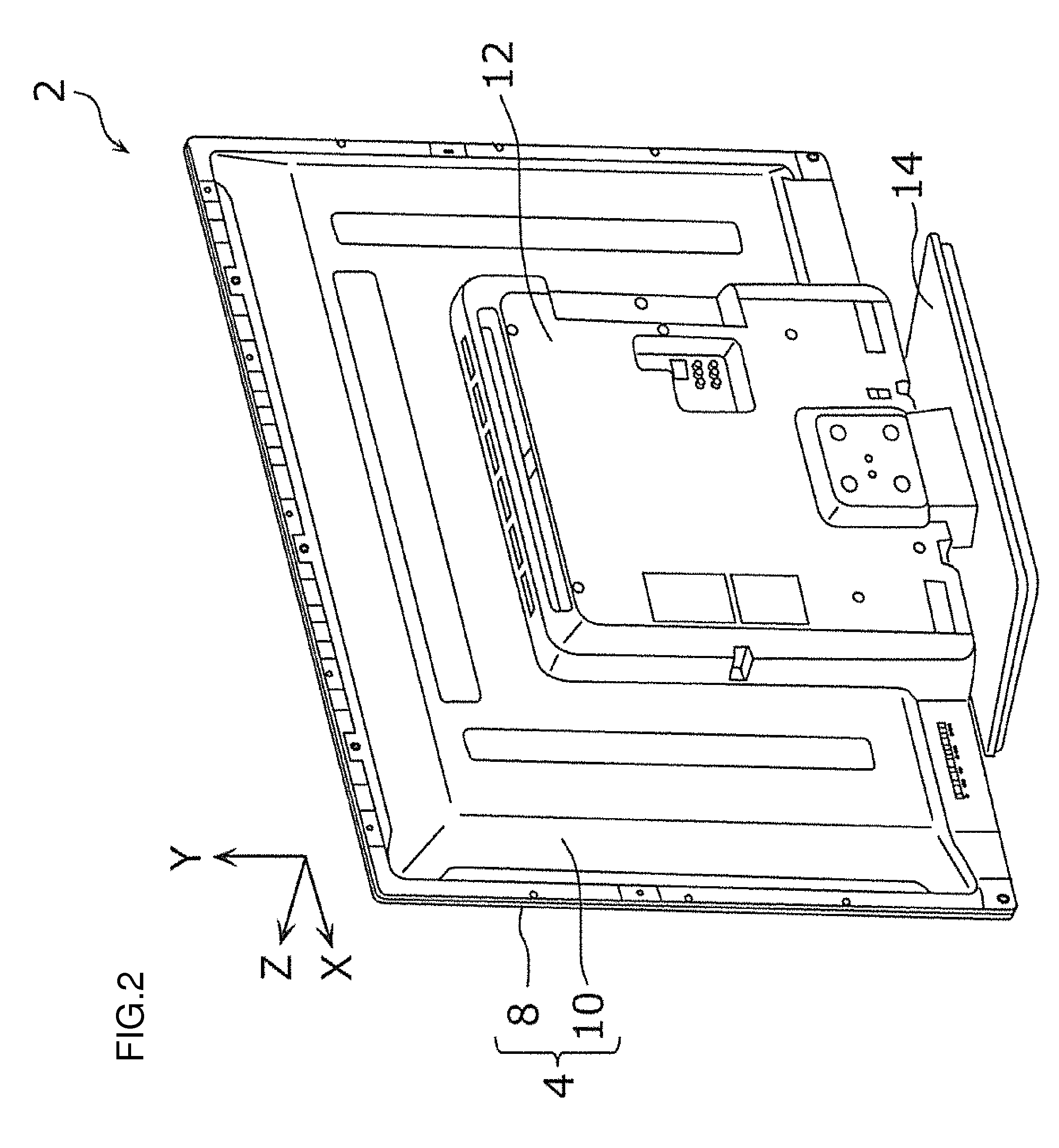
[0040]First, the overall configuration of the display device according to the first preferred embodiment will be described with reference to FIGS. 1 through 3. FIG. 1 is a perspective view showing the front side of the display device according to the first preferred embodiment. FIG. 2 is a perspective view showing the back side of the display device according to the first preferred embodiment. FIG. 3 is a perspective view showing the back side of the display device according to the first preferred embodiment in a state in which the rear cover is removed from the rear frame.

[0041]As shown in FIG. 1, the display device 2 is equipped with a casing 4, a liquid crystal panel 6 (constituting the display panel) installed within the casing 4, and a backlight unit (not shown). The display device 2 of the present preferred embodiment preferably is a liquid crystal television receiver that is equipped with a downlight-type backlight unit, for example.

[0042]The casing 4 preferably includes a fr...

second preferred embodiment

[0064]Next, the configuration of the display device according to a second preferred embodiment of the present invention will be described with reference to FIG. 11. FIG. 11 is a perspective view of key portions showing a state before a first speaker of the display device according to the second preferred embodiment is sandwiched between the rear frame and the rear cover. Note that in each of the following preferred embodiments, the same symbols are assigned to the constituent elements that are the same as in the first preferred embodiment above, and the description thereof will be omitted.

[0065]As shown in FIG. 11, in the display device of the present preferred embodiment, cylindrical protrusions 54 are respectively provided on a pair of brackets 22A of a first speaker 16A. The pair of protrusions 54 are disposed so as to be separated by the interval D1. Moreover, a pair of circular indents 56 (constituting the first mounting member) are provided for each first speaker in the outer ...

third preferred embodiment

[0069]Next, the configuration of the display device according to a third preferred embodiment of the present invention will be described with reference to FIGS. 12 and 13. FIG. 12 is a perspective view of key portions showing a state before a third speaker of the display device according to the third preferred embodiment is sandwiched between the rear frame and the rear cover. FIG. 13 is a sectional view showing a state in which the third speaker is sandwiched between the rear frame and the rear cover.

[0070]As shown in FIGS. 12 and 13, in the display device of the present preferred embodiment, any one of three size types of speaker, i.e., large, medium, and small,—in concrete terms, first speakers 16, second speakers 20, and third speakers 60 (constituting the speaker)—are capable of being mounted on the rear frame 10B and the rear cover (not shown).

[0071]The third speakers 60 have a third size that is even smaller than the second size of the second speakers 20. Each of the third sp...


PUM


Abstract

A display device includes a liquid crystal panel, a rear frame and a rear cover disposed on a back side of the liquid crystal panel and including an opening, first protrusions on the rear frame, second protrusions on the rear frame and disposed on the side opposite from the opening, with the first protrusions being arranged between the opening and the second protrusions, a first size speaker capable of being mounted on the first protrusions, a second size speaker capable of being mounted on the second protrusions, and a covering surface on the rear frame and the rear cover.

Description

BACKGROUND OF THE INVENTION[0001]1. Field of the Invention[0002]The present invention relates to a display device for displaying images.[0003]2. Description of the Related Art[0004]Known display devices are equipped with a backlight unit that directs light onto a back surface of a display panel, such as a liquid crystal television receiver (for example, see Japanese Patent Application Laid-Open Publication No. 2012-249331). A display panel, a backlight, a speaker, and the like, for example, are built in the casing of such a display device. Among these, a speaker is mounted on a speaker mounting structure that is installed in the casing.[0005]The sound quality and sound volume output from a speaker are generally related to the size of the speaker. The tendency is for quality and volume to be higher the larger the speaker is. For this reason, the size of the speaker may be selected as appropriate according to the display device specifications during the design stage of the display dev...

Claims


Application Information

Patent Timeline
Patent Type & Authority Applications(United States)
IPC IPC(8): H04N5/64
CPCH04N5/64H04N5/642G06F1/1605
Inventor SUZUKI, HIROTSUGUMIYAJIMA, KAZUTOSHI
Owner FUNAI ELECTRIC CO LTD
Why Eureka
Try Eureka