Fuel reformer for internal-combustion engine

a fuel reformer and internal combustion engine technology, which is applied in the direction of machines/engines, mechanical equipment, electric control, etc., can solve the problems of reducing the flammability deteriorating and reducing the density of the reforming component in the egr gas, so as to improve the fuel reforming capacity of the fuel reformer catalyst and improve the efficiency of the internal combustion engine. , the effect o

Active Publication Date: 2015-03-19
DENSO CORP
View PDF5 Cites 27 Cited by
  • Summary
  • Abstract
  • Description
  • Claims
  • Application Information

AI Technical Summary

Benefits of technology

[0009]The catalyst recovery control of the present disclosure when a predetermined fuel cut execution condition is satisfied (e.g., at a time of a slowdown of the internal-combustion engine), a fuel cut which stops injection of both of the main fuel and the reforming-fuel is performed. During such a fuel cut, by maintaining both of the EGR valve and the throttle valve in a valve open state, additional air (i.e., oxygen) is introduced into the EGR passage for an increased supply of oxygen to the fuel reformer catalyst. In such manner, the carbon deposited on the fuel reformer catalyst is burned promptly, and the fuel reforming capacity of the fuel...

Problems solved by technology

However, in such a system that utilizes a fuel reformer catalyst, carbon in the EGR gas may deposit on the reformer catalyst and, over time, accumulation of carbon deposits on the fuel reformer catalyst may deteriorate the fuel reforming capacity of the fuel reformer catalyst.
Therefore, when the catalyst recovery control is performed during an operati...

Method used


Image

  • Fuel reformer for internal-combustion engine
  • Fuel reformer for internal-combustion engine
  • Fuel reformer for internal-combustion engine

Examples


Embodiment Construction

[0022]An embodiment which realizes the present disclosure is described.

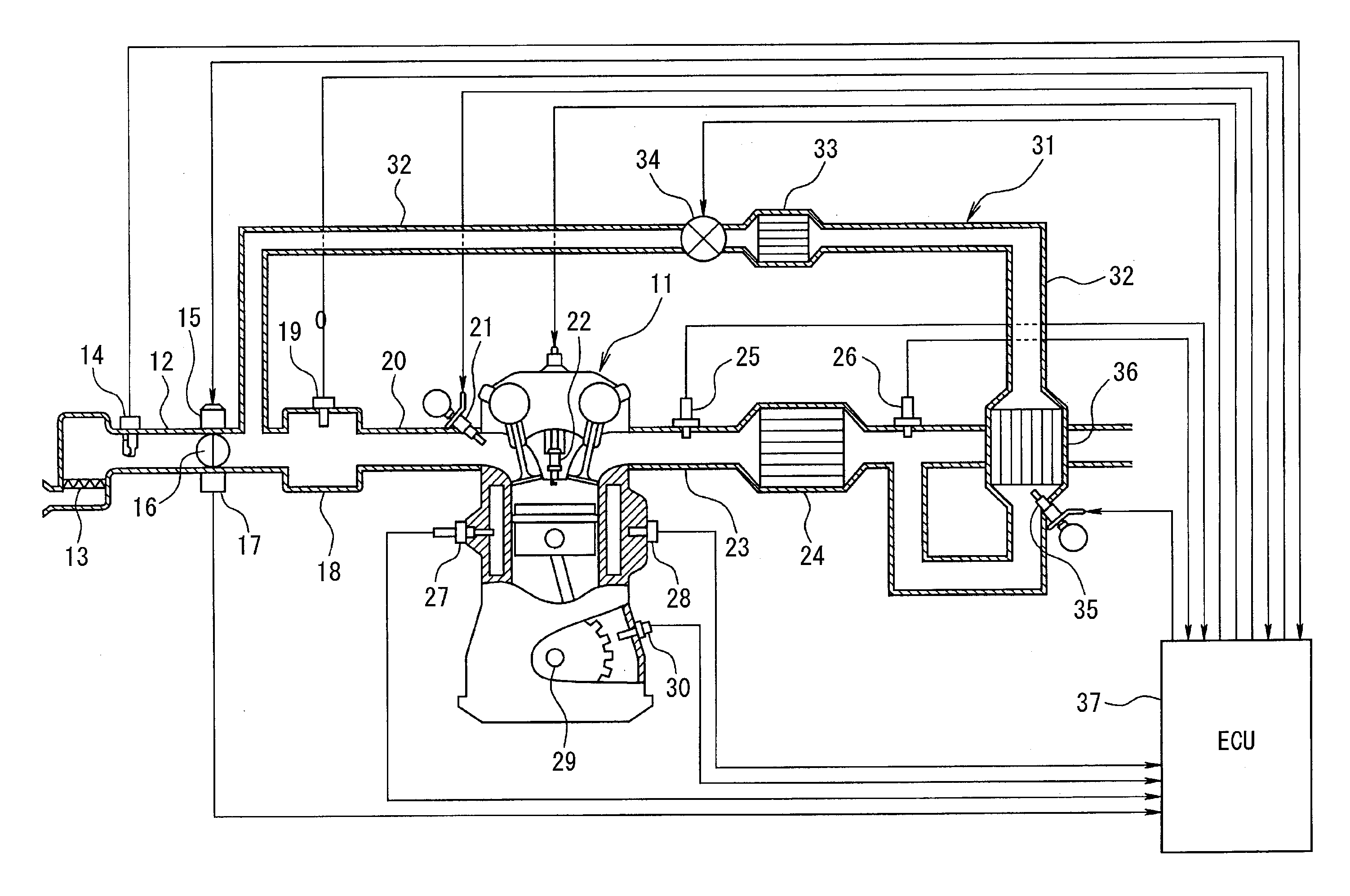
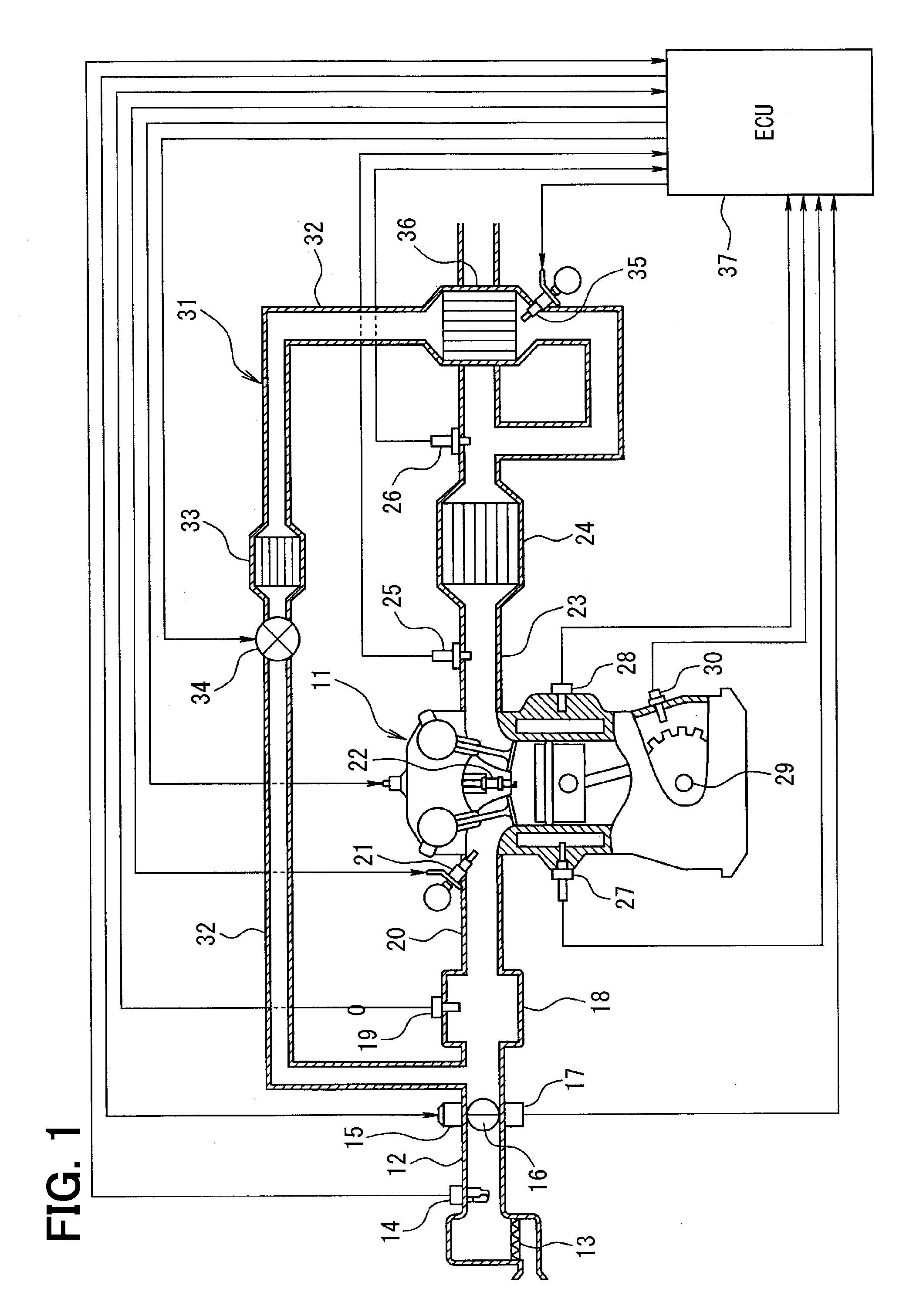
[0023]First, based on FIG. 1, an outline configuration of an entire engine control system is described.

[0024]An air cleaner 13 is disposed at the most upstream part of an air-intake pipe 12 (i.e., an air-intake passage) of the engine 11 which is an internal-combustion engine, and an air flow meter 14 which detects an intake air amount is disposed on a downstream side of the air cleaner 13. On the downstream side of the air flow meter 14, a throttle valve 16 whose opening degree is adjusted by a motor 15 as well as a throttle opening sensor 17 which detects the opening degree (i.e., a throttle opening) of the throttle valve 16 are disposed.

[0025]Further, a surge tank 18 is disposed on the downstream side of the throttle valve 16, and this surge tank 18 has an intake-pipe-pressure sensor 19 which detects an intake pipe pressure is disposed thereon. Further, an intake manifold 20 which introduces air into each of th...


PUM


Abstract

A fuel reformer includes a reforming-fuel injection valve and a fuel reformer catalyst disposed in an EGR pipe and performs a catalyst recovery control when a preset fuel cut execution condition is satisfied. In the catalyst recovery control, a fuel reforming capacity of the fuel reformer catalyst is recovered by stopping an injection of a main fuel and an injection of a reforming-fuel, while supplying additional air to the catalyst by maintaining both of an EGR valve and a throttle valve in a valve open state. Further, in the catalyst recovery control, temperature and a carbon deposit amount of the fuel reformer catalyst are estimated or detected based on which of an opening of the EGR valve and an opening of the throttle valve are adjusted. As a result, fuel reforming capacity is recovered without decreasing a fuel consumption rate improvement effect and a worsening of exhaust emission or drivability.

Description

CROSS REFERENCE TO RELATED APPLICATION[0001]The present application is based on and claims the benefit of priority of Japanese Patent Application No. 2013-191171, filed on Sep. 13, 2013, the disclosure of which is incorporated herein by reference.TECHNICAL FIELD[0002]The present disclosure generally relates to a fuel reformer for an internal-combustion engine having a fuel reformer catalyst.BACKGROUND INFORMATION[0003]A technique for reforming fuel for an internal-combustion engine to improve a fuel consumption rate is proposed in a patent document 1 (i.e., JP-A-2009-144612). The proposed technique includes a reforming-fuel injection valve which injects a reforming-fuel into an EGR passage and a fuel reformer catalyst which reforms the reforming-fuel within the EGR passage. The EGR passage partially returns an exhaust gas of the internal-combustion engine from an exhaust passage to an air-intake passage as an EGR gas. Then, the reforming-fuel injected by the reforming-fuel injection...

Claims


Application Information

Patent Timeline
IPC IPC(8): F02D41/00F02B43/12F02B51/02F02B17/00
CPCF02D41/0055F02B51/02F02B43/12F02B17/00F01N5/02F01N2240/30F01N2610/03F02D41/0065F02D41/123F02D2041/0017F02D2200/0802F02M26/15F02M26/35F02M26/36Y02T10/12Y02T10/30Y02T10/40
Inventor INUZUKA, HIROYUKIOBAYASHI, HIDEKIMIZOBUCHI, TAKESHI
Owner DENSO CORP
Why Eureka
Try Eureka