

Imaging probe and method of obtaining position and/or orientation information
Active Publication Date: 2015-03-19
EZONO
View PDF1 Cites 20 Cited by
- Summary
- Abstract
- Description
- Claims
- Application Information
AI Technical Summary
Benefits of technology
The patent describes a system that uses a magnetometric detector to measure the position and orientation of an elongate medical device, such as a cannula, during a medical procedure. This information can be used to create a three-dimensional map or panoramic map of the area being treated. The system uses an inertial measurement unit, such as an accelerometer, to estimate the secondary magnetic field and can also use markings on the device to help with positioning. Overall, the system allows for more accurate and precise navigation during medical procedures.
Problems solved by technology
It has proven challenging, however, to precisely detect the needle's end point in the ultrasound image.
It is considered a disadvantage of the system that it cannot be moved once calibrated.
Method used
View moreImage
Smart ImageViewing Examples

Examples
first embodiment
[0081]FIG. 4 shows schematically three examples of images of the patient's tissue with the position and orientation of cannula superimposed according to the invention;
second embodiment
[0082]FIG. 5 shows schematically a magnetometric detector according to the invention;
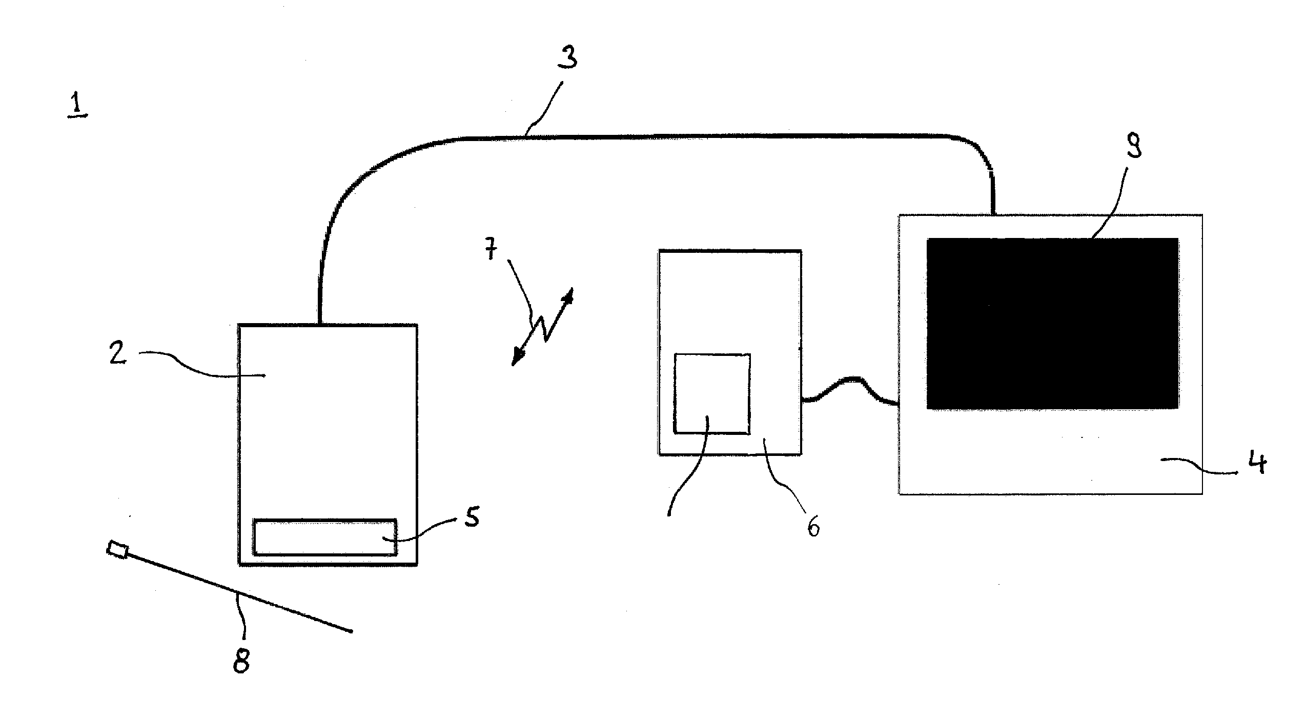
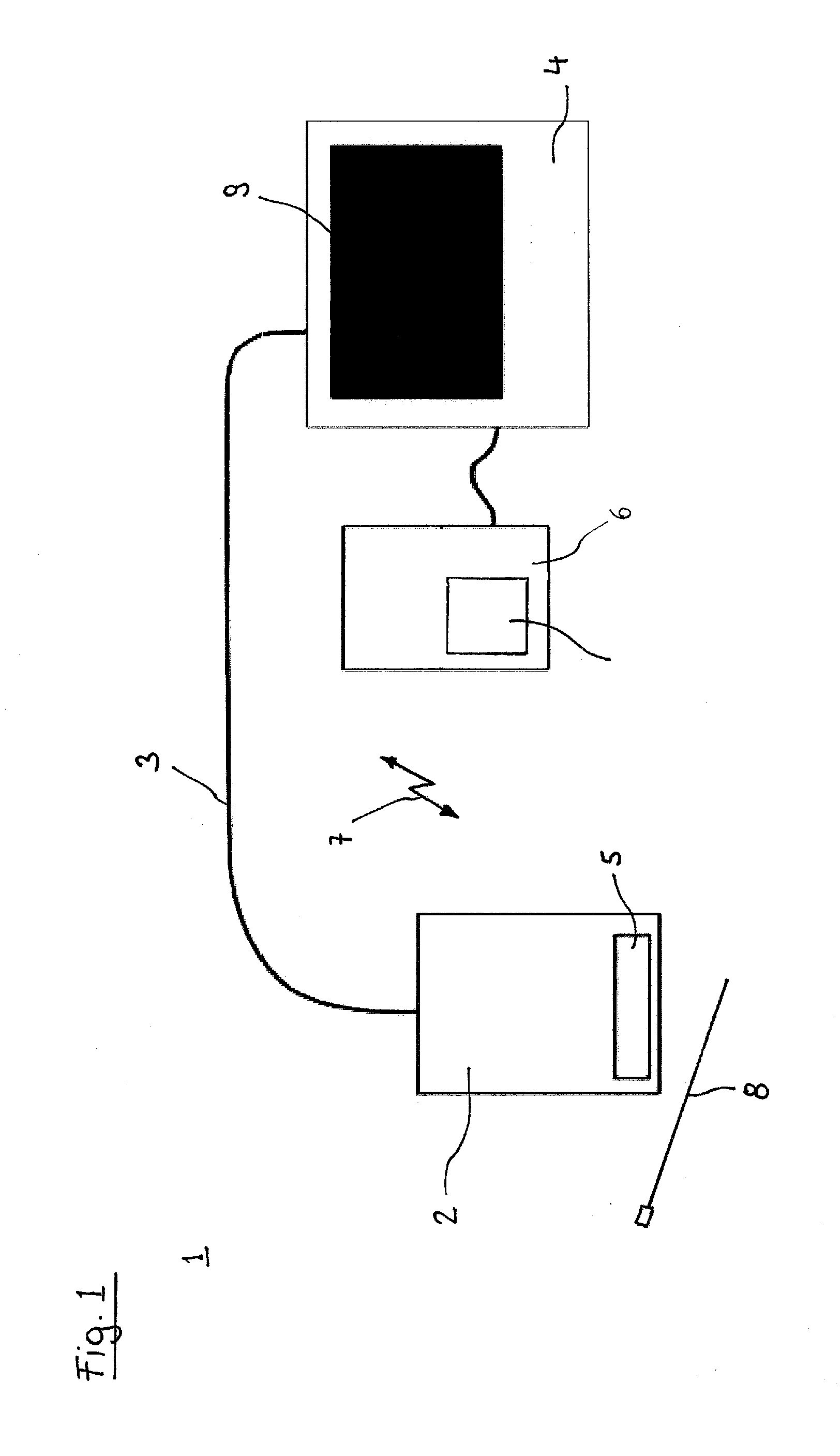
[0083]FIG. 6 shows a system of an ultrasound imaging probe and the magnetometric detector according FIG. 5;
[0084]FIG. 7 shows the absolute gradient field strength in the embodiment of FIGS. 5 and 6 as a function of the needle's distance from the imaging plane of the ultrasound imaging plane; and
[0085]FIG. 8 shows a magnetization apparatus for magnetizing a cannula according to the invention.
Login to View More PUM
 Abstract
A method of obtaining information about the position and / or orientation of a magnetic component relatively to a magnetometric detector, the magnetic component and the magnetometric detector being moveable independently from each other relatively to a static secondary magnetic field, the method comprising the steps of: measuring in the presence of the combination of both the magnetic field of the magnetic component and the static secondary magnetic field essentially simultaneously the strength and / or orientation of a magnetic field at at least a first position and a second position spatially associated with the magnetometric detector, the second position being distanced from the first position; and combining the results of the measurements to computationally eliminate the effect of the secondary magnetic field and derive the information about the position and / or orientation of the magnetic component.
Description
FIELD OF THE INVENTION[0001]The invention relates to methods of obtaining information about the position and / or orientation of a magnetic component relatively to a magnetic detector. It further relates to systems of an imaging probe for imaging at least part of the tissue of a patient and a magnetic detector for detecting the position and / or orientation of the magnetic component relatively to the magnetometric detector. It moreover relates to a medical device at least a portion of which is insertable into the tissue of the patient, the medical device comprising a magnetic component, and to a method of obtaining position and / or orientation information about at least a part of a medical device. Finally, the invention relates to an apparatus for magnetizing an elongate medical device.BACKGROUND OF THE INVENTION[0002]In numerous medical procedures that involve the insertion of a medical device into a patient's tissue, e.g. minimally invasive procedures and local anesthesia, it can be of...
Claims
Login to View More Application Information
Patent Timeline
 IPC IPC(8): A61B5/06G01B7/00H01F13/00A61B8/14A61B8/00G01R33/02G01R35/00
CPCA61B5/062G01R33/02G01B7/003H01F13/003A61B8/14A61B8/4254G01R35/005A61B5/0536A61B8/0833A61B34/20A61B2034/2051G01R33/0206G01N29/24A61B8/4494H01F7/0273
InventorHENKEL, ROLFVENTURA SOBRINO PATINO, ELISEOVON OFFENBERG SWEENEY, ROBERTDUNBAR, ALLAN
OwnerEZONO