
Liquid ejection apparatus

Active Publication Date: 2015-03-26
BROTHER KOGYO KK
View PDF1 Cites 3 Cited by
  • Summary
  • Abstract
  • Description
  • Claims
  • Application Information

AI Technical Summary

Benefits of technology

The present invention provides a liquid ejection apparatus and method that can accurately control the amount of liquid being ejected from a tank. This is achieved by controlling a drive and a pump to ensure that all the liquid in the tank flows to the supply flow passage, and then using a controller to execute a second control in which the pump and drive are used to discharge the liquid from the supply flow passage to achieve a predetermined range of liquid level in the ejection opening portion. This invention can improve the accuracy of liquid ejection and prevent leakage of liquid from the tank.

Problems solved by technology

If the liquid is discharged using a pump, however, the liquid may be discharged with poor accuracy, in other words, a remaining amount of the liquid may greatly deviate from the proper remaining amount of liquid.

Method used


Image

  • Liquid ejection apparatus
  • Liquid ejection apparatus
  • Liquid ejection apparatus

Examples


examples satisfying

[0061 the above-described relationship include the following. For example, it is assumed that the total of the target ink-discharge amounts at S1-S3 is 40 ml. Assuming that all this total of ink is discharged by the driving of the pump 51, the amount of ink to be discharged may deviate by 4 ml (40 ml*0.1) at the largest which is greater than 3.5 ml. In this case, the amount of ink discharged unfortunately exceeds the permissible range. To address this problem, it is assumed that the target ink-discharge amount is 20 ml at S1, 5 ml at S2, and 15 ml at S3, for example. In this case, the amount of ink to be discharged may deviate by 1.2 ml ((20 ml+15 ml)*0.02+5 ml*0.1) at the largest which is less than 3.5 ml. Accordingly, the deviation of the remaining amount of the ink falls within the permissible range. The number of ink ejections is set at a value obtained by dividing 20 ml by an amount of ink to be ejected per ejection at S1, and the number of ink ejections is set at a value obtai...


PUM


Abstract

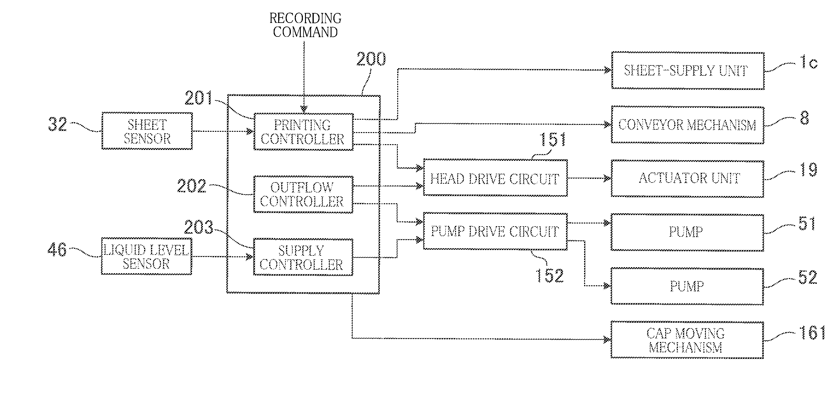
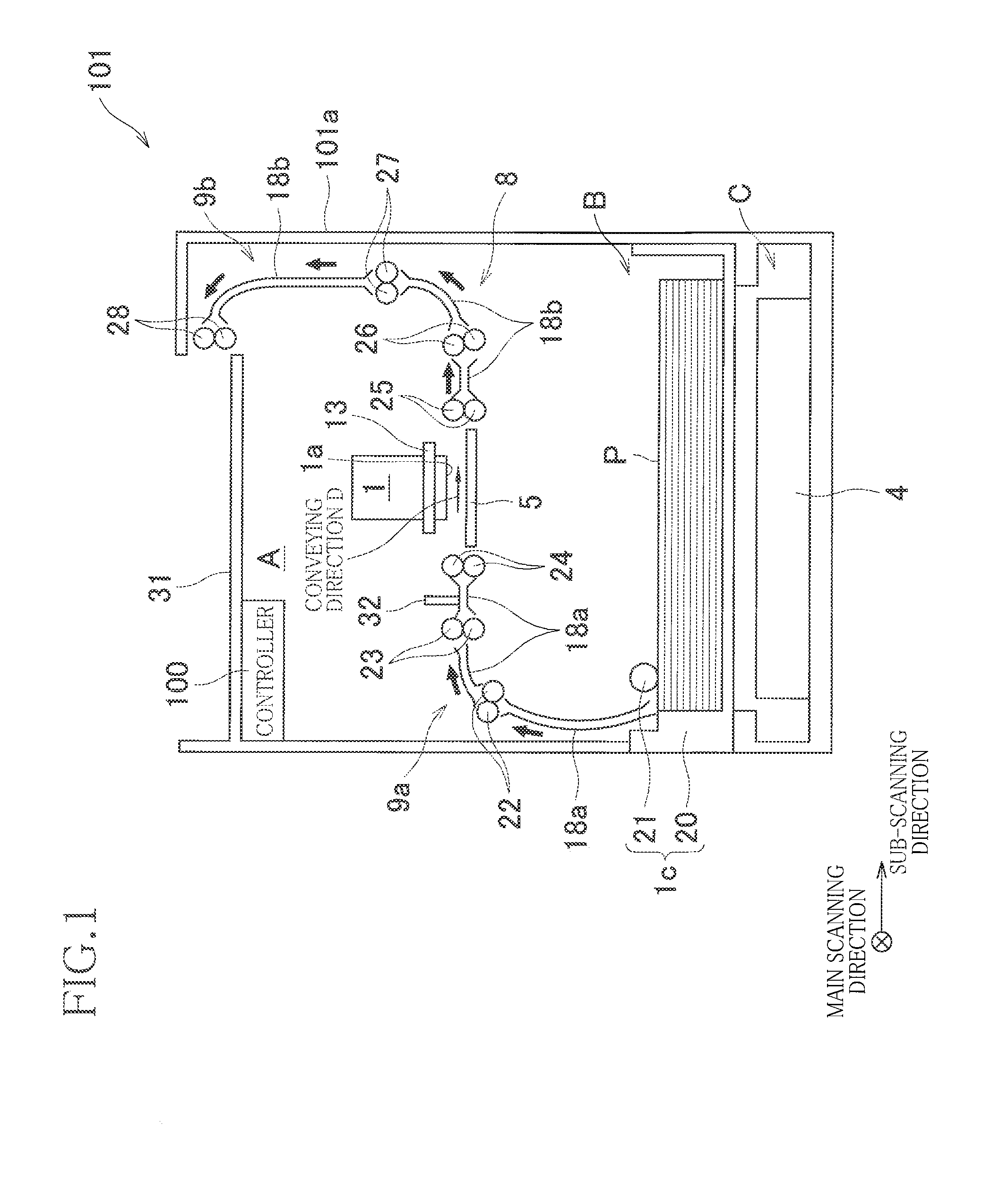
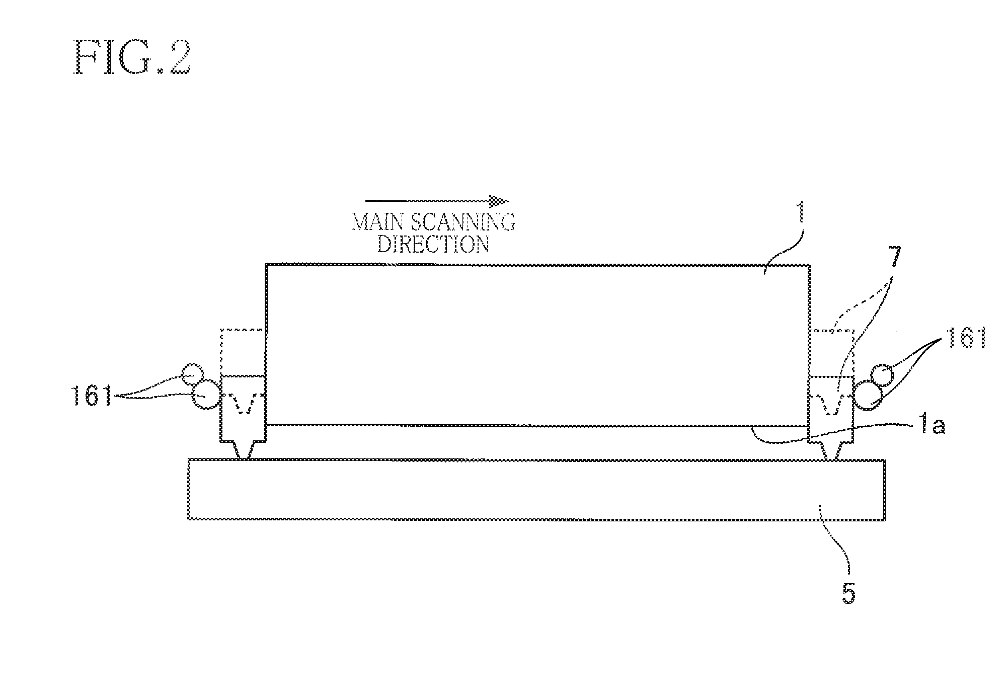
A liquid ejection apparatus includes: a liquid ejection head including (i) an ejection opening portion, (ii) a supply flow passage, and (iii) an actuator, a first tank connected to the liquid ejection head to supply liquid to the supply flow passage; a pump for forcing the liquid in the first tank into the supply flow passage; and a controller. The controller executes: a first control for driving the actuator, or the actuator and the pump such that all the liquid in the first tank flows to the supply flow passage; and a second control for, after a completion of the first control, driving the actuator in a state in which the pump is stopped, to discharge the liquid in the supply flow passage from the ejection opening portion such that an amount of the liquid in the supply flow passage falls within a predetermined range.

Description

CROSS REFERENCE TO RELATED APPLICATION[0001]The present application claims priority from Japanese Patent Application No. 2013-200066, which was filed on Sep. 26, 2013, the disclosure of which is herein incorporated by reference in its entirety.BACKGROUND OF THE INVENTION[0002]1. Field of the Invention[0003]The present invention relates to a liquid ejection apparatus including a liquid ejection head having an ejection surface for ejecting liquid.[0004]2. Description of the Related Art[0005]There is known a printer configured such that a pump discharges ink from a tank in advance of transport of the apparatus.SUMMARY OF THE INVENTION[0006]When discharging liquid from the inside of a tank, some amount of liquid needs to remain in a head in some cases in order to prevent meniscuses from being broken and air from flowing into the head, for example. Incidentally, a large amount of liquid remaining in the head is not preferable to prevent a leakage of liquid from the head. Accordingly, the...

Claims


Application Information

Patent Timeline
IPC IPC(8): B41J2/175
CPCB41J2/17596B41J2/175B41J2/18B41J29/38B41J2002/17576
Inventor ITO, TAKASHI
Owner BROTHER KOGYO KK
Learn More