
Light Fixture Mounting Assembly

a technology for mounting assemblies and light fixtures, applied in the direction of lighting support devices, lighting and heating apparatus, protection devices for lighting, etc., can solve the problems of incompatibility of design and installation, inconvenience or impossible,

Active Publication Date: 2015-03-26
MAN D TEC
View PDF4 Cites 16 Cited by
  • Summary
  • Abstract
  • Description
  • Claims
  • Application Information

AI Technical Summary

Benefits of technology

The patent text describes a light fixture mounting assembly that is designed to be installed into a panel with a hole for light. The assembly includes a lamp housing with an opening and a detent to engage the panel's surface. The assembly also has a spring clip-type retainer to hold the lamp housing in place and a hose clamp-type retainer to keep it in place. The technical effect of this assembly is a more secure and reliable installation of a light fixture in a panel.

Problems solved by technology

Securing a light fixture from above a ceiling panel requires access to the space above the ceiling panel which, in some cases, may be inconvenient or impossible—discouraging or preventing the use of a light fixture mounting assembly adapted to be secured from above.
Since light fixture mounting assemblies adapted to be secured from above are known to be incompatible with being secured from below, light fixtures have been adapted specifically to be secured from below and without requiring any access to the space above a ceiling panel.
But these designs are known to be incompatible for installation from above.
This can be problematic where, for example, designers wish to standardize fixtures across areas with different ceiling access availability.

Method used


Image

  • Light Fixture Mounting Assembly
  • Light Fixture Mounting Assembly
  • Light Fixture Mounting Assembly

Examples


Embodiment Construction

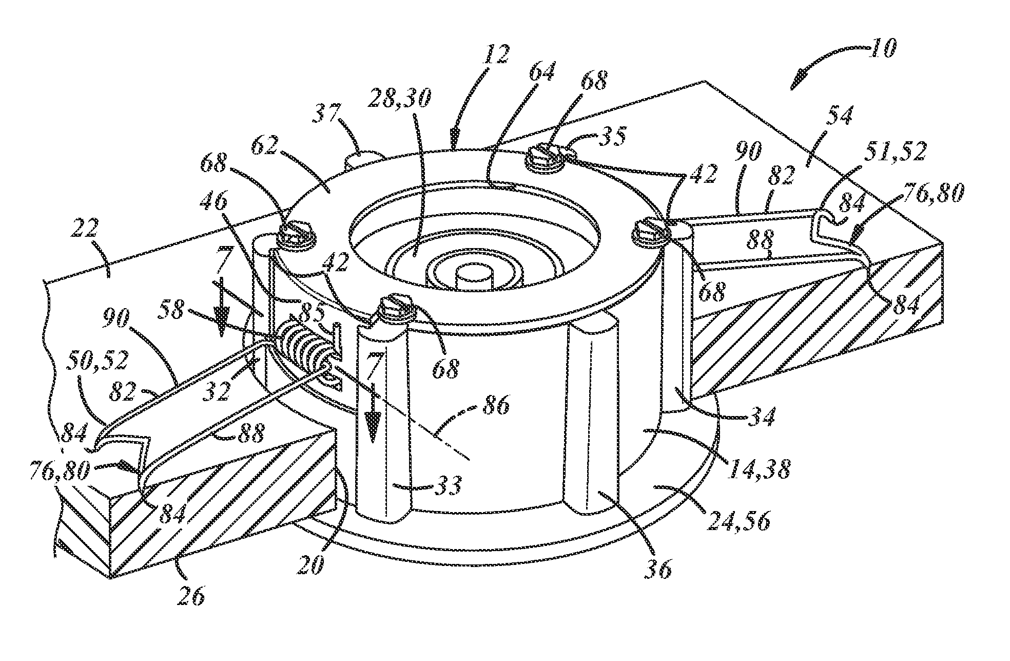
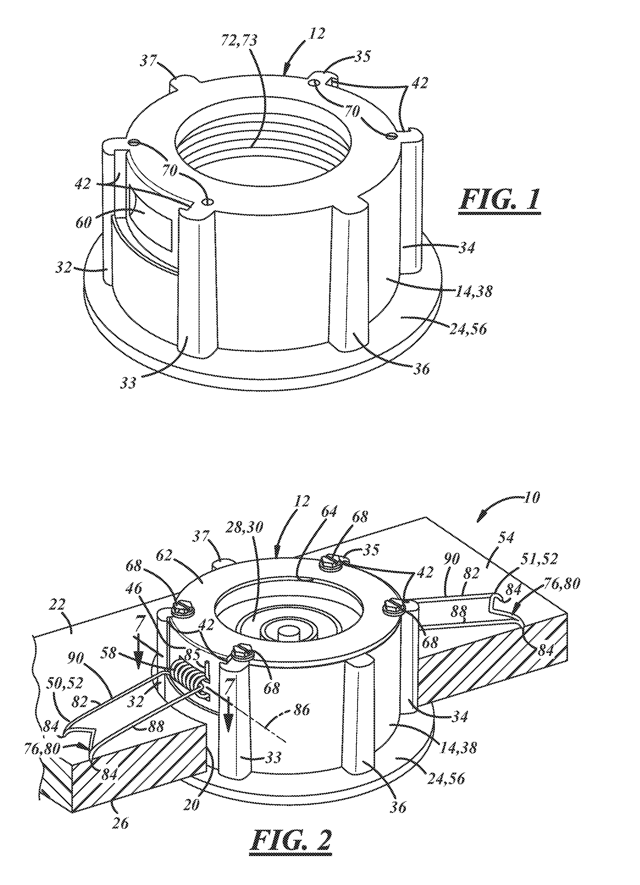
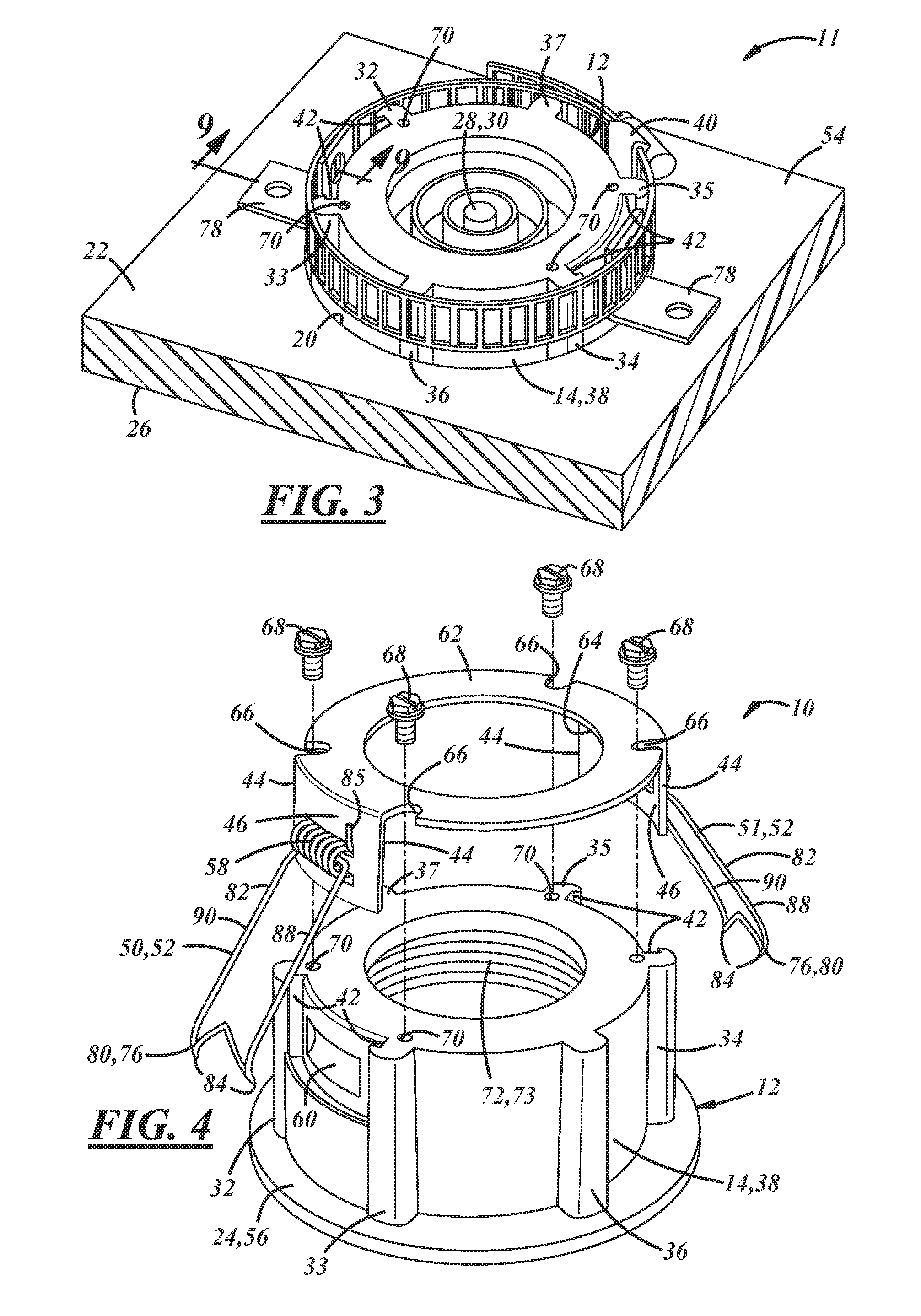
[0021]A first light fixture mounting assembly for supporting a light fixture in a panel having a through-hole for receiving such a fixture is generally shown at 10 in FIGS. 1, 2, and 4-8. A second light fixture mounting assembly is generally shown at 11 in FIGS. 3 and 9. As best shown in FIGS. 3 and 5, both the first mounting assembly 10 and the second mounting assembly 11 may include the same lamp housing 12. In other words, the lamp housing 12 may be common to both the first and the second mounting assemblies.

[0022]The lamp housing 12 may include a sidewall 14 and an opening 16 defined by a rim 18 at one end of the sidewall 14. The housing 12 may be configured to be received into an installed position in a through-hole 20 in a panel such as a ceiling panel 22. A detent 24 may extend outward from the sidewall 14 in a position to engage an outer surface 26 of the panel 22, e.g., a lower surface 26 of a ceiling panel 22, when the housing 12 is in the installed position in the through...


PUM


Abstract

A light fixture mounting assembly that includes a lamp housing having a sidewall and an opening defined by a rim at one end of the sidewall and a detent extending outward from the sidewall in a position to engage an outer surface of a panel when the housing is in an installed position. A lamp module is carried within the lamp housing and comprises a lamp positioned to emit light through the housing opening. The lamp housing is configured to carry either a spring clip-type retainer or a hose clamp-type retainer to hold the lamp housing in the installed position.

Description

CROSS-REFERENCES TO RELATED APPLICATIONS[0001]Not ApplicableSTATEMENT REGARDING FEDERALLY SPONSORED RESEARCH OR DEVELOPMENT[0002]Not ApplicableBACKGROUND[0003]1. Field[0004]This application relates generally to light fixture mounting assemblies for supporting a light fixture in a panel having a through-hole for receiving such a fixture.[0005]2. Description Of Related Art Including Information Disclosed Under 37 CFR 1.97 and 1.98[0006]Light fixture mounting assemblies configured to support a light fixture in a ceiling panel are generally designed to be inserted into a ceiling panel through-hole from below the ceiling panel, but differ in that they are adapted to be secured in the through-hole either from above or from below the ceiling panel. Securing a light fixture from above a ceiling panel requires access to the space above the ceiling panel which, in some cases, may be inconvenient or impossible—discouraging or preventing the use of a light fixture mounting assembly adapted to b...

Claims


Application Information

Patent Timeline
IPC IPC(8): F21V21/04
CPCF21V21/047F21V21/046F21V21/042
Inventor MANDY, TERRY ROYMANDY, DALTON JOHNMANDY, BRANDON ROYFLAKE, TYLER
Owner MAN D TEC
Learn More