Method and device for determining a breathing movement of an object under examination

a breathing movement and object technology, applied in the field of methods and devices for determining the breathing movement of an object under examination, can solve the problems of patient sterility requirements, patient fitted with chest belt, and inability to accurately reconstruct images to form a three-dimensional image, etc., to achieve the effect of improving the adaptation of the mathematical breathing model

Inactive Publication Date: 2015-03-26
SIEMENS AG
View PDF3 Cites 7 Cited by
  • Summary
  • Abstract
  • Description
  • Claims
  • Application Information

AI Technical Summary

Benefits of technology

[0012]Embodiments of the invention include determining a breathing movement of an object under examination, such as a human patient. In the first method step, a mathematical breathing model may be received, loaded or obtained. The mathematical breathing model can be used to describe a displacement of a thoracic cage of the object under examination over time. Mathematical models are known per se. They can, for example, be obtained empirically or by physical modeling. Mathematical models generally comprise parameters to be determined, a priori determined constants and mathematical linking of the parameters and constants. The determination of the parameters enables the mathematical breathing model to be adapted to the real individual object under examination. For example, the mathematical breathing model enables a prognosis of the temporal course of the displacement of the thoracic cage. This then makes is possible to wait for the time at which the thoracic cage is motionless in order to then take one or more images. A simple breathing model could, for example, comprise a sine function with which frequency and amplitude are defined as parameters to be determined.
[0018]In an exemplary embodiment, the camera and the projection means are aligned at least approximately identically. This feature may ensure that the projection for a recording using the camera is projected optimally onto the thoracic region of the object under examination and changes induced by the breathing movement are effectively acquired by the camera.
[0021]In an exemplary embodiment, the at least one thoracic image encompassing the thoracic region comprises depth information. If the adjustable camera supplies an image encompassing at least the thoracic region of the object under examination and containing depth information, the projection means can be aligned in one step such that the thoracic region is effectively covered by the projected, structured image pattern and the projection means can be adjusted such that one or more parameters that influence the structured image pattern can be adjusted. This can avoid iteration steps that may have been necessary in the case of a thoracic image without depth information.
[0025]This supplement to the method improves the adaptation of the mathematical breathing model in that further information is taken into account with respect to the breathing of the object under examination. This can be done using a sequence of thermography or thermal images to encompass the nasal region of the object under examination. Here, use is made of the effect that, on exhaling, heated air flows out of the nose which is visible in the thermography images. An image processing method detects the temperature change and converts it into a change in the displacement of the thoracic cage. Vice versa, a temperature drop in the region of the nostril is assigned to an enlargement of the displacement of the thoracic cage of the object under examination. The mathematical breathing model is then also adapted in dependence on the assigned change in the displacement of the thoracic cage of the object under examination. In one exemplary embodiment, the additional adaptation consists of determining the average from the displacement of the thoracic cage originating from the sequence of images of the thoracic region of the object under examination and from the assigned displacement of the thoracic cage of the object under examination obtained by means of the thermography images.

Problems solved by technology

Movements during the acquisition of a plurality of images would, for example, have the result that the reconstruction of the images to form a three-dimensional image could only be performed imprecisely or would even be impossible.
One of the drawbacks of this method is that the patient has to be fitted with the chest belt and, in many cases, the chest belt is also subject to sterility requirements.

Method used


Image

  • Method and device for determining a breathing movement of an object under examination
  • Method and device for determining a breathing movement of an object under examination
  • Method and device for determining a breathing movement of an object under examination

Examples


Embodiment Construction

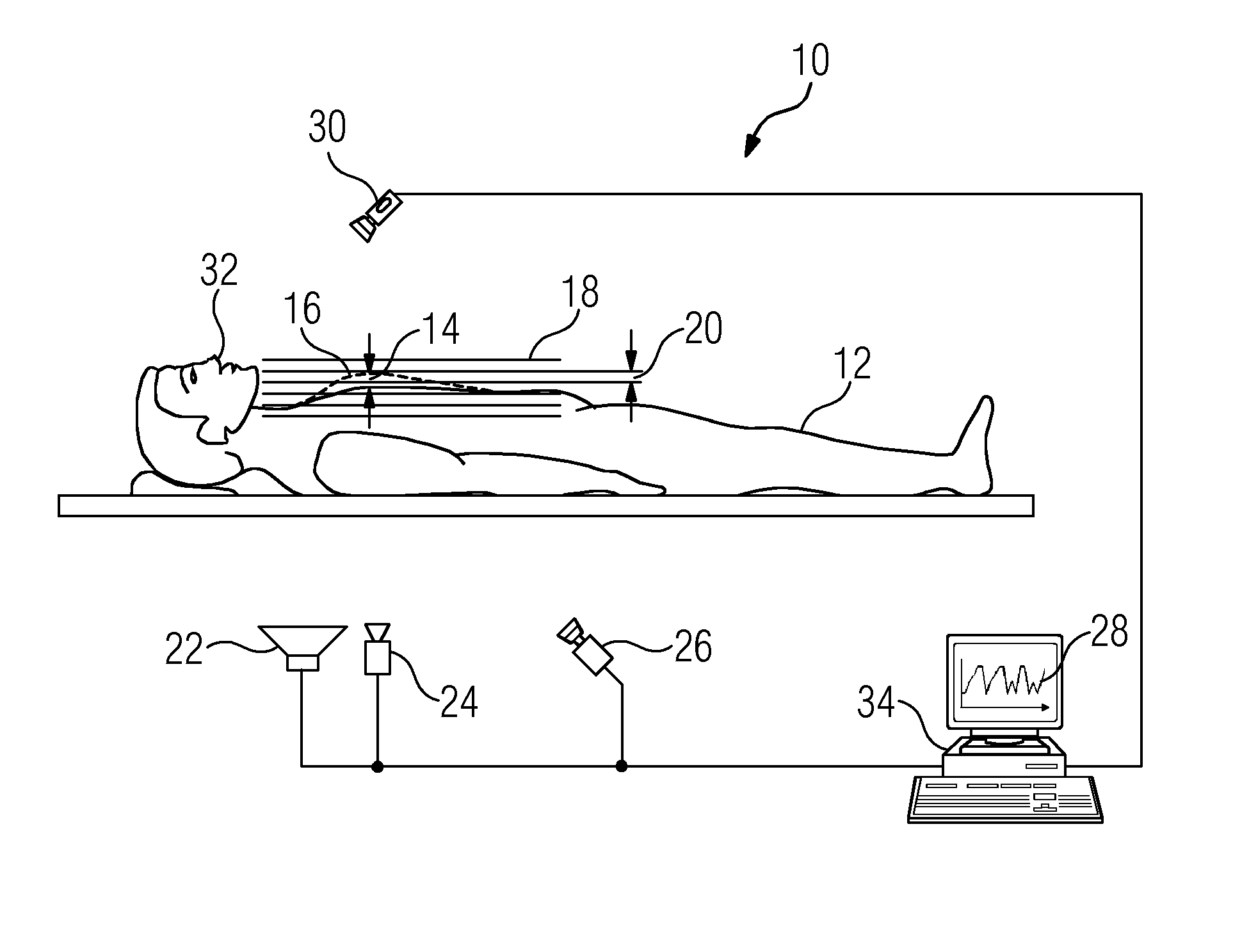
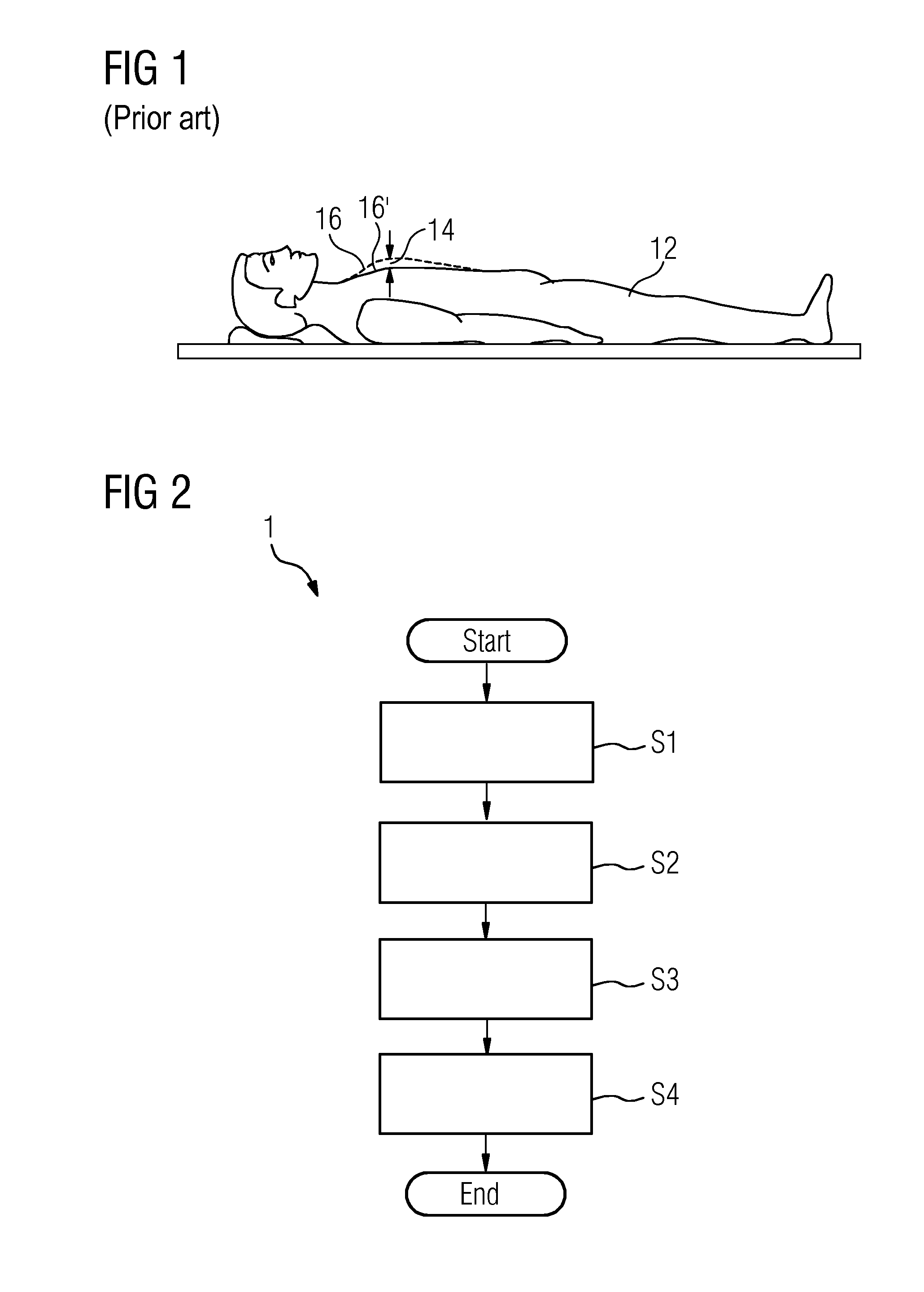
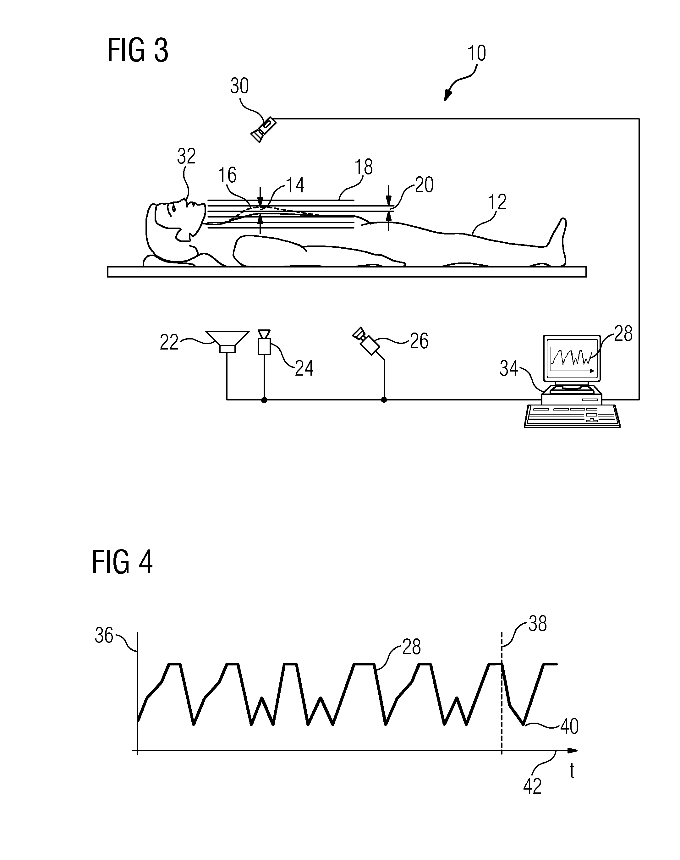
[0041]FIG. 1 is a depiction of an object under examination 12, here a human patient, with indicated breathing movement. The breathing movement is shown by a displacement 14 of the thoracic cage, wherein in FIG. 1, the two extreme states, namely complete inhalation and complete exhalation are depicted. The location 16 of the thoracic cage after inhalation is indicated by a dashed line, the exhalation causes the thoracic cage to move in the dorsal direction until the location 16′, which is identified by a continuous line, is reached.

[0042]FIG. 2 shows by way of example a flow diagram of a method according to the embodiments of invention 1 for determining a breathing movement of an object under examination. The method 1 may comprise the method steps S1 to S4. It starts, “Start”, with method step S1 and ends, “End”, after method step S4. The individual method steps may be as follows:

[0043]S1) reception of a mathematical breathing model, said mathematical breathing model comprising a dis...


PUM


Abstract

A method and device for determining a breathing movement of an object under examination is provided for the method includes determining a breathing movement of an object under examination and includes receiving a mathematical breathing model, the mathematical breathing model including a displacement of a thoracic cage of the object under examination over time, using a projection means to project a structured image pattern onto a sagittal plane and onto a thoracic region of the object under examination, using a camera to record a sequence of at least two images of the thoracic region of the object under examination, and adapting the mathematical breathing model at least in dependence on the recorded sequence of images of the thoracic region of the object under examination. The invention also describes a corresponding device for determining a breathing movement of an object under examination.

Description

CROSS-REFERENCE TO RELATED APPLICATIONS[0001]This application claims priority to DE Application No. 102013219232.0, having a filing date of Sep. 25, 2013, the entire contents of which are hereby incorporated by reference.FIELD OF TECHNOLOGY[0002]The following relates to a method for determining a breathing movement of an object under examination. The following also relates to a corresponding device for determining a breathing movement of an object under examination.BACKGROUND[0003]Examinations of patients and surgical interventions are frequently supported by imaging systems, such as X-ray units, computed tomography devices or magnetic resonance tomography devices. In such cases, there is frequently a requirement to record one or more images at a specific time during a respiratory cycle. One reason for this is that, in a state at the end of an expiration or inhalation, the thoracic cage is virtually motionless for a short period of time so that a plurality of images can be taken, fo...

Claims


Application Information

Patent Timeline
Patent Type & Authority Applications(United States)
IPC IPC(8): A61B5/113A61B5/01A61B5/00
CPCA61B5/1135A61B5/015A61B5/0077A61B5/1128
Inventor HAIDER, SULTANPOPESCU, STEFAN
Owner SIEMENS AG
Why Eureka
Try Eureka