Adjustable headband

a headband and adjustable technology, applied in the field of adjustable headbands, can solve the problems of difficult operation of the bowable fastening mechanism of u.s. pat. no. 5, use of a different type of suspension, and difficulty in adjusting the size of the band, so as to increase the size of the loop of the headband

Active Publication Date: 2006-05-18
MINE SAFETY APPLIANCES CO +1
View PDF22 Cites 10 Cited by
  • Summary
  • Abstract
  • Description
  • Claims
  • Application Information

AI Technical Summary

Benefits of technology

[0009] In one embodiment, the plurality of connectors on the first end section are slots. The at least one cooperating connector can, for example, be a projection. More than one projection can attached to the connecting member. In another embodiment, each of the projections includes a first surface which is angled to facilitate sliding of the projections over the slots of the first end section when the first end section and the second end section are moved relative to each other to decrease the size of the loop of the headband. In this embodiment, each of the projections also includes a second surface that is angled to abut one of the slots of the first end section when in the engagement position and to provide resistance to movement of first end section and second end section relative to each other in a direction to increase the size of the loop of the headband when in the engagement position.
[0011] In another aspect, the present invention provides a headband for use in a headgear support including a first end section having a plurality of spaced slots and a second end section including a fastener attached adjacent the end thereof. The fastener includes a flexible connecting member and at least one cooperating connector attached to the connecting member and biased by the connecting member in an engagement position with at least one of the plurality of slots of the first end section to hold the headband in a selected loop configuration. The connecting member is movable to a disengage position upon application of a generally lateral force to the fastener to cause the cooperating connector to disengage from the at least one of the plurality of slots of the first end section to enable increasing the size of the loop of the headband.
[0012] The at least one cooperating connector can, for example, be a projection. As described above, the projection can include a first surface which is angled to facilitate sliding of the projections over the slots of the first end section when the first end section and the second end section are moved relative to each other to decrease the size of the loop of the headband. In this embodiment, the projection can further include a second surface that is angled to abut one of the slots of the first end section when in the engagement position and to provide resistance to movement of first end section and second end section relative to each other in a direction to increase the size of the loop of the headband when in the engagement position.

Problems solved by technology

While this type of headband is relatively simple to manufacture (in part because separate mechanical fasteners or adjustment mechanisms are generally not required), users of such bands often have difficulty adjusting the band size while wearing the suspension.
This inconvenience often results in the use of a different, more expensive type of suspension, such as a ratchet-type suspension system as, for example, described in U.S. Pat. No. 4,942,628.
Unfortunately, it can be difficult to operate the bowable fastening mechanism of U.S. Pat. No. 5,896,586 with only one hand.

Method used


Image

  • Adjustable headband
  • Adjustable headband
  • Adjustable headband

Examples


Embodiment Construction

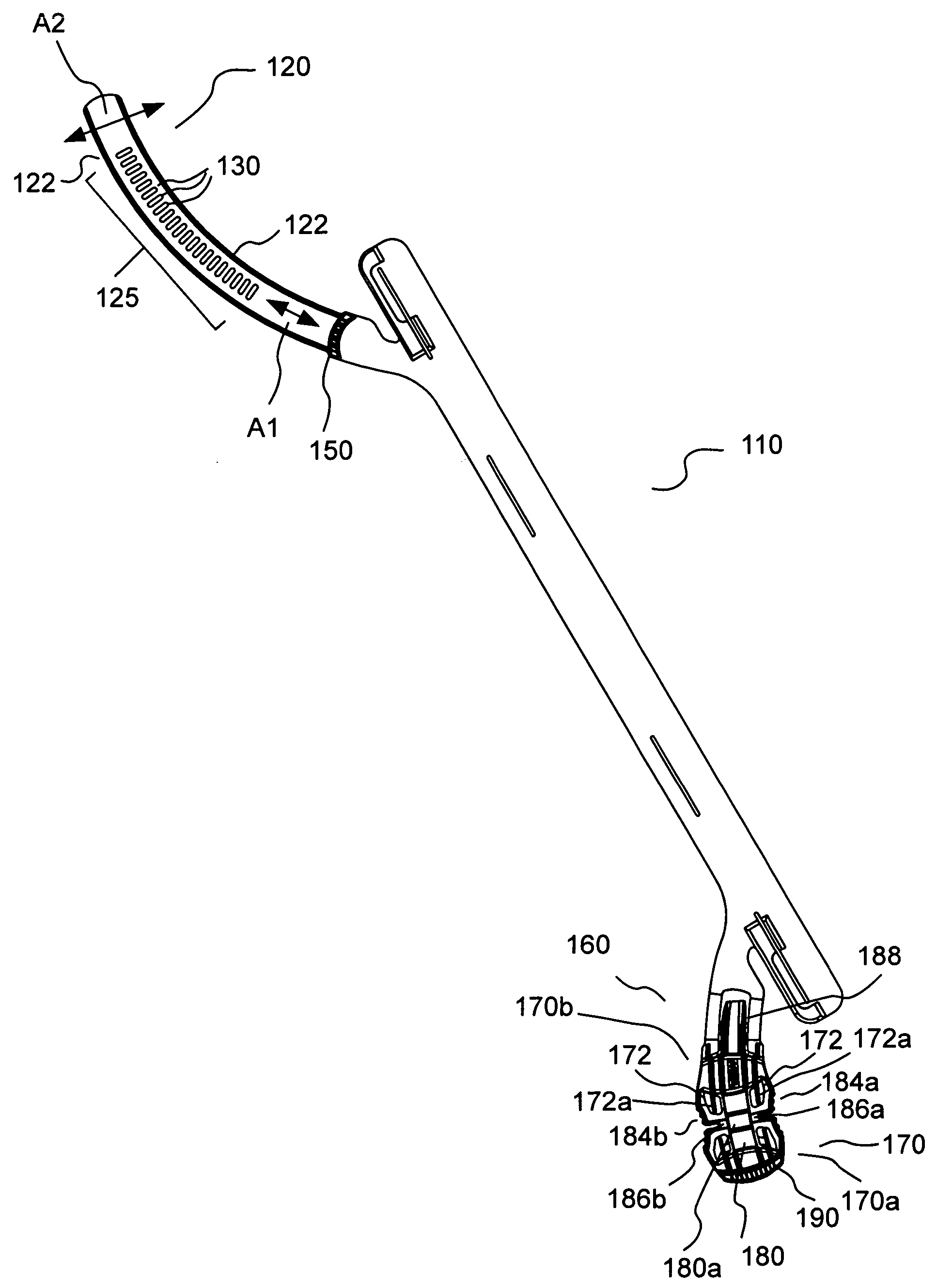
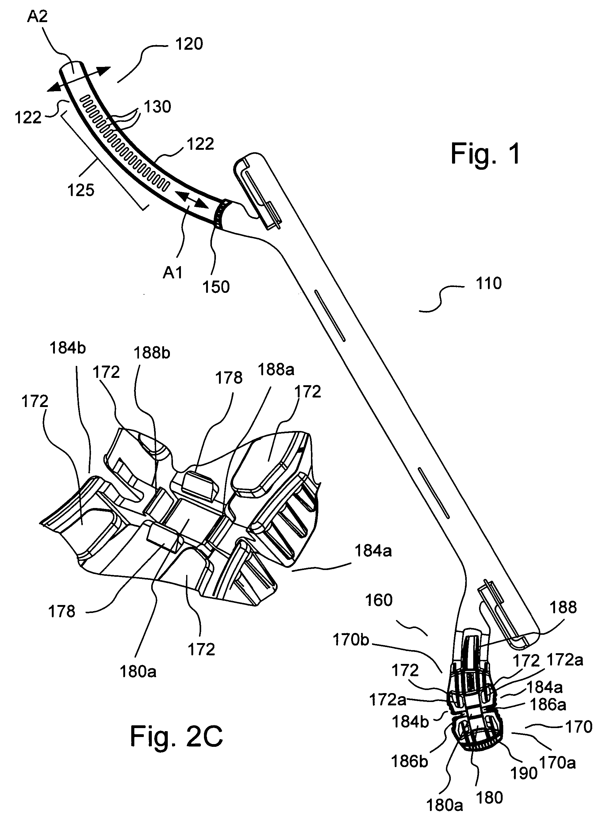
[0037]FIG. 1 illustrates an embodiment of a headband or head strap 110 of the present invention for use in a headgear support. Headband 110 is, for example, a flexible member that can be molded from one or more suitable polymeric materials to extend around the head of the user. Headband 110 can, for example, be formed from an integral or monolithic piece of polymeric material or can, for example, be co-molded or otherwise fabricated from two or more polymeric materials. A first end 120 and second end 160 overlap, preferably at the back of the wearer's head (see, for example, FIGS. 4A and 4B). Headband 110 may be straight from end to end, in which case first end 120 and second end 160 will overlap on the head of the user. On the other hand, first end 120 and second end 160 may extend downwardly in the rear portion of headband 110 across the nape of the neck. The latter embodiment is illustrated in FIGS. 1 through 5. Regardless of which type of headband 110 is used, overlapping ends 1...


PUM


Abstract

A headband for use in a headgear support includes a first end section having a plurality of spaced connectors and a second end section including a fastener attached adjacent the end thereof. The fastener includes a connecting member to which at least one cooperating connector is attached. The connecting member biases the cooperating connector in an engagement position with at least one of the plurality of connectors of the first end section to hold the headband in a selected loop configuration. The fastener further includes at least a first flexible release member. Upon application of a force to the first release member, the first flexible release member is movable to a release position (or range of positions) in which the first release member abuts the connecting member to cause the connecting member to flex to a disengage position (or range of positions) in which the cooperating connector is disengaged from the at least one the plurality of connectors of the first end section to enable increasing the size of the loop of the headband.

Description

FIELD OF THE INVENTION [0001] The present invention relates generally to adjustable headbands and, particularly, to adjustable headbands for use in headgear, including, for example, personal protective products such as protective helmets, faceshields and welding shields. BACKGROUND OF THE INVENTION [0002] Most types of protective helmets worn by workers to protect them from falling objects have a suspension system. The suspension system or headgear support, along with the helmet shell, act to absorb the shock of a falling object striking the top of the worker's head. The suspension system also serves as a support that holds the helmet or faceshield on the worker's head. [0003] The suspension is often a web-like support system comprising two or more strips of material that are arranged to cross each other. The ends of the strips are, for example, attached at four or more points around the circumference of the helmet. A headband is then typically attached to the four or more points of...

Claims


Application Information

Patent Timeline
Patent Type & Authority Applications(United States)
IPC IPC(8): A42B1/22
CPCA42B3/145Y10T24/45079A44B11/223
Inventor KETTERER, KEVIN R.ABY-EVA, GREGOIRE B.HERSICK, F. JOSEPHZELLER, PAUL A.SCOCCIMERRA, ANTHONY JR.BECHTOLD, ROBERT E.
Owner MINE SAFETY APPLIANCES CO
Why Eureka
Try Eureka