
Gear fault detection

Active Publication Date: 2015-03-26
SIKORSKY AIRCRAFT CORP
View PDF3 Cites 34 Cited by
  • Summary
  • Abstract
  • Description
  • Claims
  • Application Information

AI Technical Summary

Benefits of technology

The patent is about a method and apparatus for detecting and locating faults in a gear system by measuring the impact energy of the teeth on a shaft. The technical effect is the ability to quickly and accurately identify the location of a fault in a gear system, which can help improve maintenance and repair operations.

Problems solved by technology

Gear teeth may be subjected to degradation.
Such degradation may be due to any number of factors, such as defects in manufacturing, a breakdown of materials due to use, etc.
These techniques can detect major faults, but don't typically perform well for earlier stages of gear degradation.
Monitoring a vibration associated with split torque gearboxes may be difficult because there may be many identical or substantially similar gear meshes (e.g., the same number of gear teeth, the same shaft frequency).
A vibration signal produced by a single faulty gear may be obscured by other healthy gears with, e.g., identical gear mesh frequencies, which can make it difficult to detect and diagnose incipient failures.

Method used


Image

  • Gear fault detection
  • Gear fault detection
  • Gear fault detection

Examples


Embodiment Construction

[0014]It is noted that various connections are set forth between elements in the following description and in the drawings (the contents of which are included in this disclosure by way of reference). It is noted that these connections in general and, unless specified otherwise, may be direct or indirect and that this specification is not intended to be limiting in this respect. In this respect, a coupling between entities may refer to either a direct or an indirect connection.

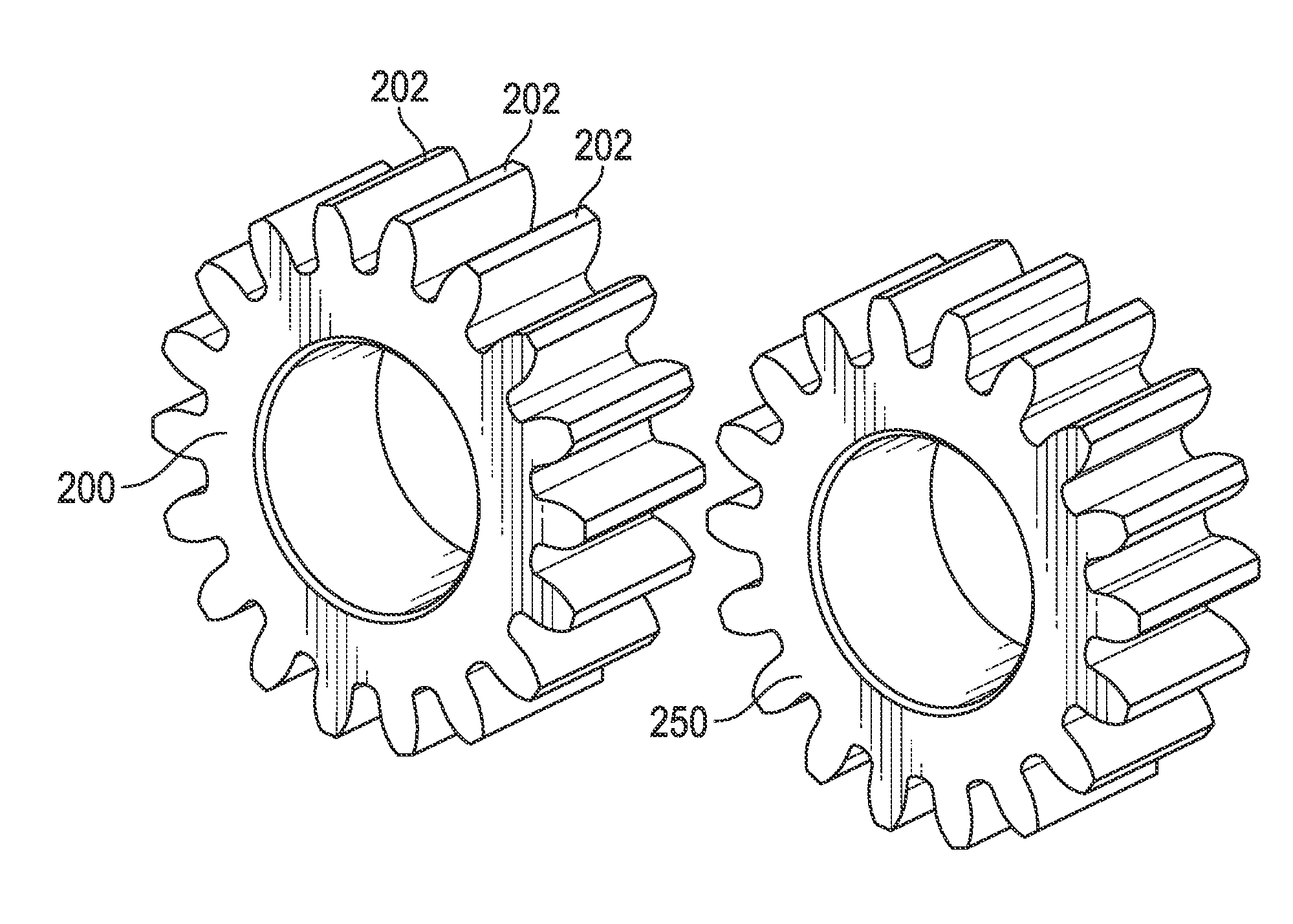
[0015]Exemplary embodiments of apparatuses, systems, and methods are described for obtaining data regarding the status or health of a gear. Such data may be analyzed at the level of a tooth of the gear. In some embodiments, a profile of a gear may be analyzed to determine if an abnormality exists with respect to the profile. When such an abnormality does exist, a determination may be made that it is likely that a tooth of the gear is degraded.

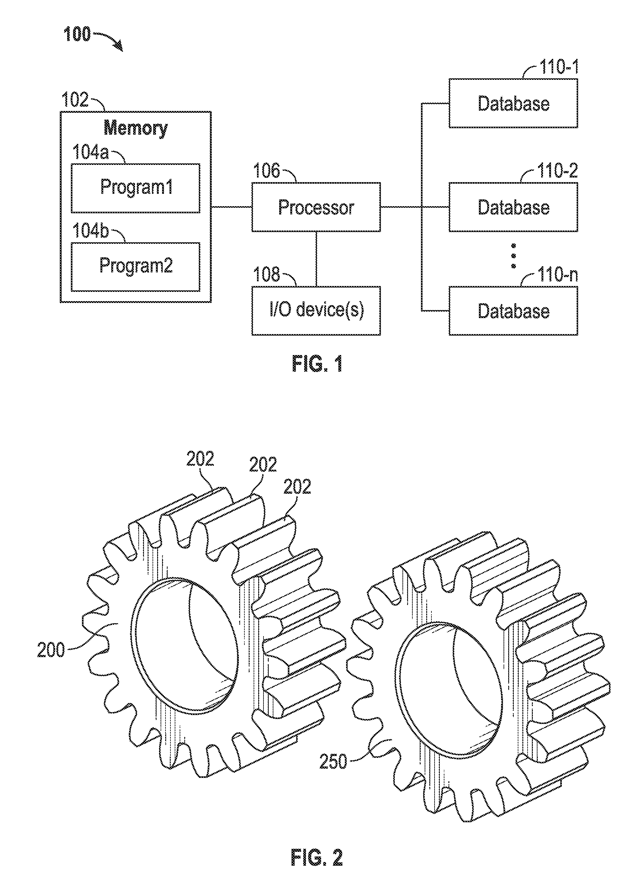
[0016]Referring to FIG. 1, an exemplary computing system 100 is shown...


PUM


Abstract

Embodiments are directed to obtaining an impact energy signal associated with each of a plurality of teeth of a gear over a revolution of a shaft associated with the gear, generating, by a computing device comprising a processor, a profile of the impact energy signal, and declaring a fault associated with an identified tooth included in the plurality of teeth based on an analysis of the profile.

Description

BACKGROUND[0001]Gear teeth may be subjected to degradation. Such degradation may be due to any number of factors, such as defects in manufacturing, a breakdown of materials due to use, etc. Current techniques use statistical or time-series features of a time-synchronous average associated with a shaft for a gear of interest. These techniques can detect major faults, but don't typically perform well for earlier stages of gear degradation.[0002]A split torque gearbox (e.g., a planetary gearbox) may share a load among multiple load paths (e.g., multiple parallel load paths). A split torque gearbox may incorporate identical or substantially similar shaft / gear configurations in parallel. Monitoring a vibration associated with split torque gearboxes may be difficult because there may be many identical or substantially similar gear meshes (e.g., the same number of gear teeth, the same shaft frequency). A vibration signal produced by a single faulty gear may be obscured by other healthy gea...

Claims


Application Information

Patent Timeline
IPC IPC(8): G01N19/08
CPCG01N19/08F16H57/01F16H2057/012G01H1/003G01M13/021G01M13/028G01N29/04G01N29/14G01N29/4454G01N29/46G01N29/50G01N2291/015G01N2291/0234G01N2291/0258G01N2291/2696
Inventor ISOM, JOSHUA D.CHAUDHRY, ZAFFIR A.ZHANG, GUICAISUN, FANPINGSHASHANKA, MADHUSUDANACHEN, YAN
Owner SIKORSKY AIRCRAFT CORP
Learn More