Steering column device

a technology of steering column and steering column, which is applied in the direction of steering column, steering parts, vehicle components, etc., can solve the problems of deteriorating productivity of steering column device and normal disengagement mechanism, and achieve the effect of enhancing ensuring the reliability of steering column device, and increasing the displacement amount of the assembling position

Active Publication Date: 2015-04-02
TOYOTA JIDOSHA KK
View PDF1 Cites 6 Cited by
  • Summary
  • Abstract
  • Description
  • Claims
  • Application Information

AI Technical Summary

Benefits of technology

The present invention relates to a steering column device, which is designed to ensure reliability and enhance productivity. The device allows for relative rotation of two brackets when an external force is applied to the disengaging mechanism, which prevents damage to the mechanism. This rotation prevents the second bracket from being assembled onto the vehicle body through the intermediation of the disengaging mechanism, which improves reliability and eliminates the need for inspection. The device can also be used as a qualified device by setting a predetermined value to prevent the load affecting the disengagement performance of the disengaging mechanism from being applied to it.

Problems solved by technology

Although there is a risk in that the disengaging mechanism is not normal, the second bracket may be assembled onto the vehicle body through an intermediation of the disengaging mechanism.
Therefore, in order to ensure reliability of the steering column device (in order to secure the disengagement performance of the disengaging mechanism), all of the steering column devices need to undergo inspection for the disengaging mechanism immediately before each steering column device is assembled onto the vehicle body, and hence productivity of the steering column device is deteriorated.

Method used


Image

  • Steering column device
  • Steering column device
  • Steering column device

Examples


first embodiment

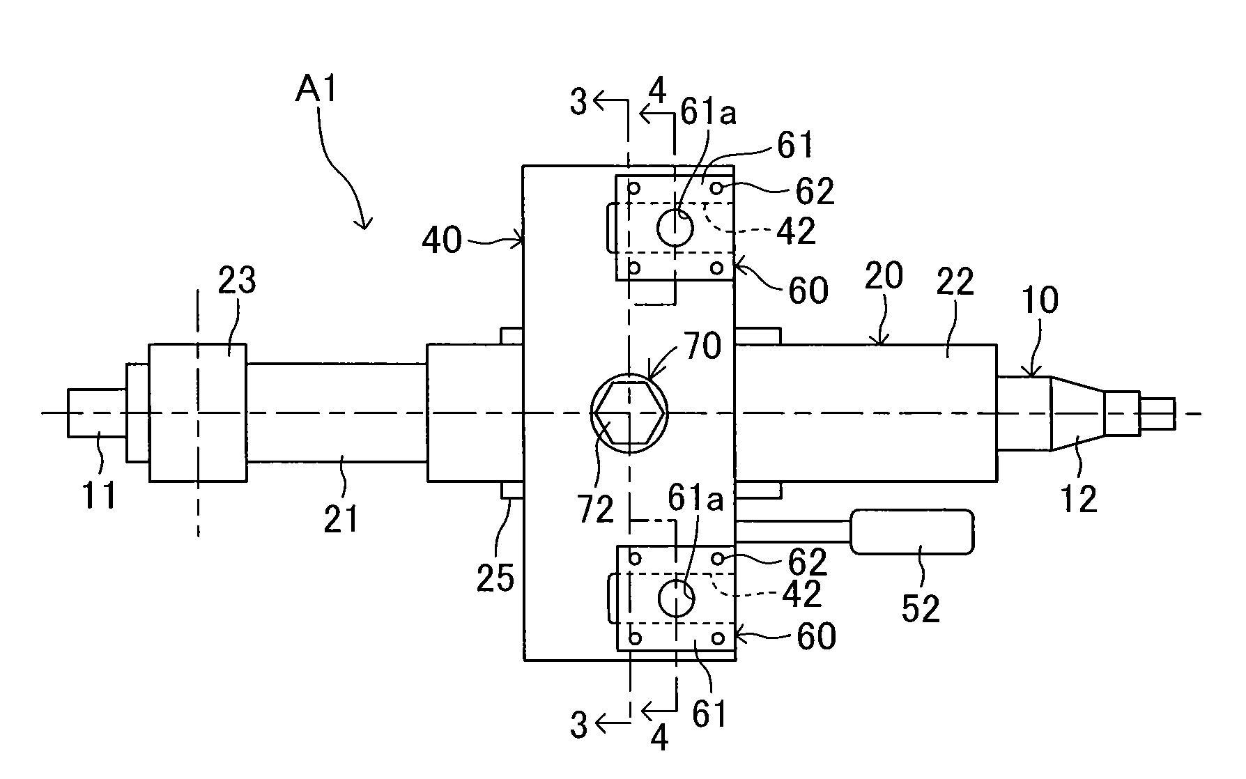
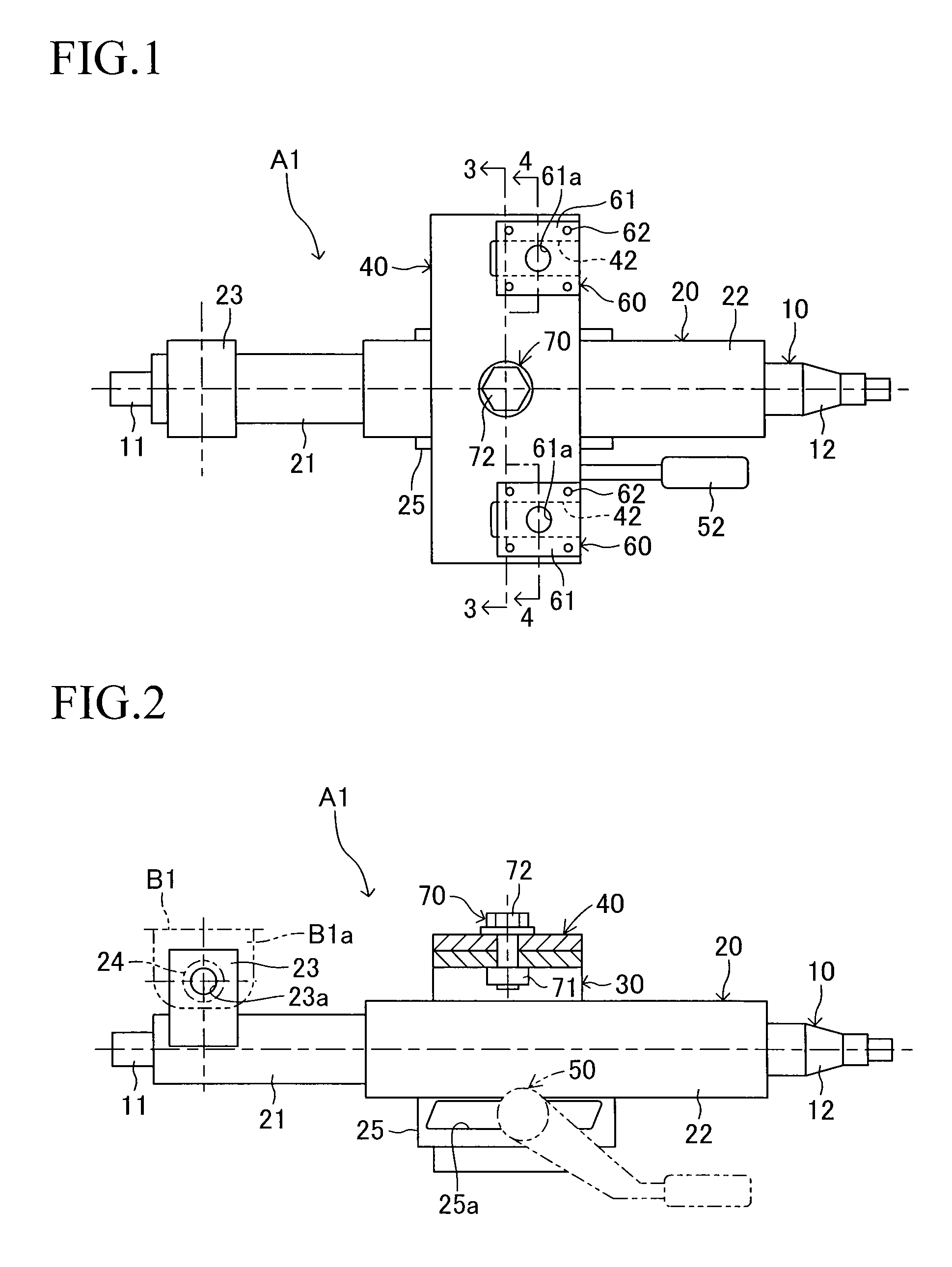
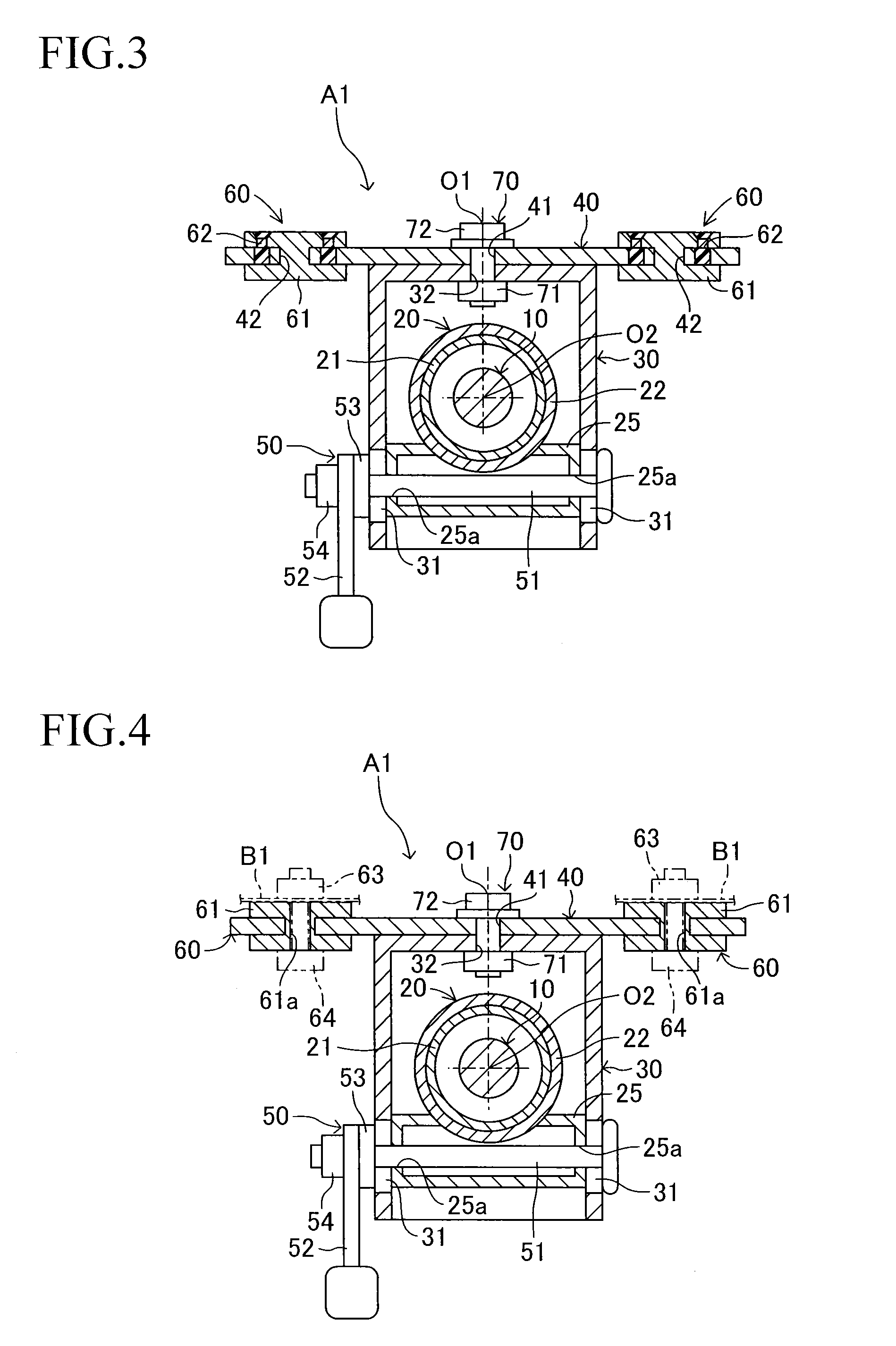
[0026]Now, embodiments of the present invention are described with reference to the drawings. FIGS. 1 to 4 schematically illustrate a steering column device according to the present invention. A steering column device A1 according to this embodiment includes a column tube 20 for supporting a steering shaft 10 in a freely rotatable manner, a first bracket 30 for supporting the column tube 20 so that the column tube 20 is adjustable in its position (adjustable in tilting and telescoping thereof), and a second bracket 40 coupled to the first bracket 30 and assembled onto a vehicle body B1 (see FIG. 4). Further, the steering column device A1 includes a locking device 50 interposed between the column tube 20 and the first bracket 30, and disengaging mechanisms 60 respectively provided on portions (right and left end portions) of the second bracket 40 to be assembled onto the vehicle body B1, and also includes a coupling mechanism 70 for coupling the first bracket 30 and the second bracke...

second embodiment

[0041]The coupling mechanism 170 includes a coupling pin 171 inserted through the mounting hole 41 of the second bracket 40 and the mounting hole 32 of the first bracket 30 when the first bracket 30 and the second bracket 40 are coupled to each other, the pair of right and left nuts 172 fixed onto the first bracket 30 in advance, and the pair of right and left bolts 173 threadedly fixed onto the nuts 172, respectively. The nuts 172 are provided on the first bracket 30 so as to respectively correspond to circular mounting holes 33 formed in the first bracket 30. The bolts 173 are threadedly fixed onto the nuts 172, respectively, through circular-arc mounting holes 43 formed in the second bracket 40 and through the circular mounting holes 33 formed in the first bracket 30. In the coupling mechanism 170, the rotation center O1 of relative rotation, which is performed in the coupling mechanism 170, is set so as to intersect the axis center O2 of the steering shaft 10, and the rotation ...


PUM


Abstract

A steering column device including a first bracket for supporting a column tube that supports a steering shaft, a second bracket coupled to the first bracket and assembled onto a vehicle body, and a disengaging mechanism provided on the second bracket that allows the column tube to be disengaged from the vehicle body forward along a column axis direction under a set load when a secondary impact is caused with a collision of a vehicle. The first bracket and the second bracket are coupled to each other through an intermediation of a coupling mechanism in a relatively rotatable manner, and a rotation center of relative rotation intersects an axis center of the steering shaft. The first bracket and the second bracket perform relative rotation when an external force exceeding a predetermined value is applied to the disengaging mechanism along the column axis direction before the first bracket, the second bracket, the disengaging mechanism are assembled onto the vehicle body.

Description

TECHNICAL FIELD[0001]The present invention relates to a steering column device applicable to a vehicle, and more particularly, to a steering column device including a first bracket for supporting a column tube that supports a steering shaft in a freely rotatable manner, a second bracket coupled to the first bracket and assembled onto a vehicle body so as to fix the column tube onto the vehicle body, and a disengaging mechanism provided on the second bracket and configured to allow the column tube to be disengaged from the vehicle body forward along a column axis direction under a set load when a secondary impact is caused in the event of collision of a vehicle, in which the first bracket, the second bracket, the disengaging mechanism, and the like are integrated with one another (formed into a subassembly) under a state before the steering column device is assembled onto the vehicle body.BACKGROUND ART[0002]The steering column device including the first bracket, the second bracket, ...

Claims


Application Information

Patent Timeline
Patent Type & Authority Applications(United States)
IPC IPC(8): B62D1/19
CPCB62D1/195
Inventor HOSHINO, SHIGERU
Owner TOYOTA JIDOSHA KK
Why Eureka
Try Eureka