
Mechanism for collecting impurities in stagnant waters

a technology of impurities and machines, applied in water cleaning, special purpose vessels, separation processes, etc., can solve the problems of insufficient equipment for collecting impurities from water surface, inefficient use, and high cost of technology

Inactive Publication Date: 2015-04-02
TECHNICKA UNIVERZITA V KOSICIACH +1
View PDF3 Cites 10 Cited by
  • Summary
  • Abstract
  • Description
  • Claims
  • Application Information

AI Technical Summary

Benefits of technology

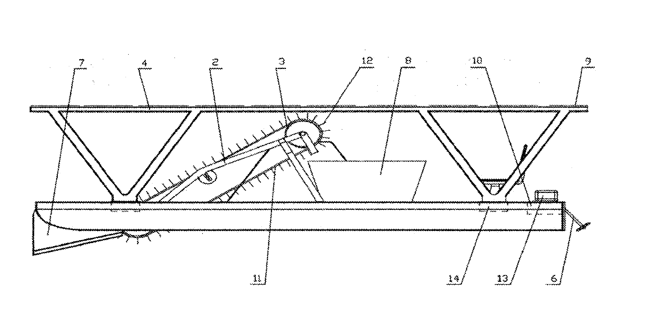
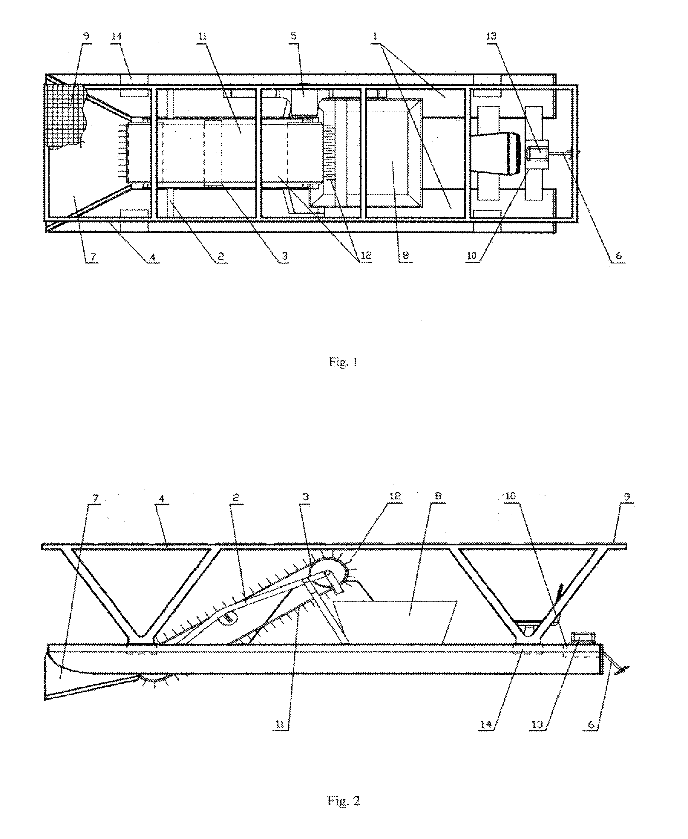
The current technology for collecting impurities from stagnant waters is not perfect, so the patent text describes a new solution using a catamaran structure. The equipment includes two hollow catamaran floats that are connected together, with operators seated at the rear side. The front part has funnel jaws for directing impurities towards the conveyor belt and then into a removable container. The conveyor belts are driven by an electric motor, and the catamaran's movement is controlled by an operator or through remote control. When the catamaran is anchored at a quay, the batteries are charged from a stationary battery charging device. The technical effects include efficient and effective collection of impurities from stagnant waters, increased efficiency of the conveyor system, and improved control over the catamaran's movement.

Problems solved by technology

They are financially expensive and can only be used very inefficiently for slow collection of impurities from the surface of stagnant waters (FR2721580A1, JP5085465A, JP10119880A, JP60053487A, SE460720B, SE452735B, U.S. Pat. No. 7,045,058B2).
This technology is expensive, the equipment has large dimensions therefore it is less mobile and consequently manoeuvrable only with difficulties on smaller dams.
These machines are not equipped for collecting impurities from water surface and cannot be operated on small bodies of water, used as sources of drinking water or for recreational purposes (CA1107661A1, DE4110722A1).
However, these are stationary devices, they can move only on the crest of the dam, thus their reach over the entire body of water is impossible (EP0520750A1, GB2365387A, WO2005097592A1, W02009030977A2, GB2026883A).

Method used


Image

  • Mechanism for collecting impurities in stagnant waters
  • Mechanism for collecting impurities in stagnant waters

Examples


Embodiment Construction

[0011]The equipment for collecting impurities in stagnant waters comprises two catamaran floats 1, having a shape of a hollow body, for example a shape of a semi-cylinder. At the front of the catamaran floats 1, there is a drum belt conveyor 3, mounted in the frame 2. The belt conveyor 3 can include a removable, perforated mesh belt 11, made of felt, textile, or plastic material or of metal, fitted with forks 12 for collecting solid and viscous impurities from the water. The impurities are gathered through the frontal funnel-shaped part—jaws 7, by the belt 11 into the removable container 8. The drive 5 of the belt 11 is an electric motor mounted at the axis of the driving drum of the belt conveyor 3. In the middle part of the catamaran floats 1 there is the drive 5 of the belt 11, connected to the batteries 14, in the rear part of the equipment there is the rudder 6 and the marine engine 13, the whole with manual control or with programmable remote control 10. At the surface of the ...


PUM

PropertyMeasurementUnit
Speedaaaaaaaaaa
Shapeaaaaaaaaaa

Abstract

The equipment for collection of impurities in stagnant waters having a catamaran design includes two catamaran floats (1) having a form of a hollow body terminated by the jaws (7), where at the front part of the catamaran floats (1) there is mounted in the frame (2) the conveyor belt (3) with the removable mesh belt (11) with fixed forks (12), with the drive (5) of the belt (11). At the middle part of the catamaran floats (1), under the conveyor belt (3), there is attached the removable container (8), in the cavity of the catamaran floats (1) there are the batteries (14) connected to the photovoltaic cells (9), which are installed on bracket (4) of the photovoltaic panels and at the end of the catamaran floats (1) there is fixed the marine engine (13), the rudder (6) and the remotely programmable control (10), and the equipment is also provided with a separate remote control—a joystick.

Description

CROSS REFERENCE TO RELATED APPLICATION[0001]This application is a national stage entry of PCT / SK2013 / 000004 filed Mar. 22, 2013, under the International Convention claiming priority over Slovakia Application No. PUV 50-2012 filed Mar. 28, 2012.TECHNICAL FIELD[0002]The technical solution relates to equipment for collecting impurities in stagnant waters, having a catamaran design and belonging to the field of shipping and float equipment, with the specific aim of collecting solid particles and viscous impurities in stagnant waters of lakes and dams.BACKGROUND ART[0003]Catamaran designs used up to now have most often been used as watercraft for sports with a power drive or with sail propulsion. They are designed on the principle of two floats such as racing catamaran structures for various sports classes or river catamarans. These types of equipment are built aerodynamically in order to achieve great speed. They are financially expensive and can only be used very inefficiently for slow...

Claims


Application Information

Patent Timeline
IPC IPC(8): E02B15/10
CPCE02B15/104B63B1/121B63B35/32B63B2035/008B63J3/04B63J2003/003Y02T70/00
Inventor SEBO, DUSANBADIDA, MIROSLAVSEBO, JURAJFEDORCAKOVA, MONIKA
Owner TECHNICKA UNIVERZITA V KOSICIACH
Learn More