
Radio frequency identification display device

a display device and radio frequency identification technology, applied in the field of radio frequency identification display devices, can solve the problems of repeatedly reading data, operator's inability to instantly judge whether the read data is correct, and possible malfunction of reading data, so as to improve efficiency, save time effective stock taking, and improve display effect

Inactive Publication Date: 2015-04-09
LIU TAI HWA +1
View PDF3 Cites 5 Cited by
  • Summary
  • Abstract
  • Description
  • Claims
  • Application Information

AI Technical Summary

Benefits of technology

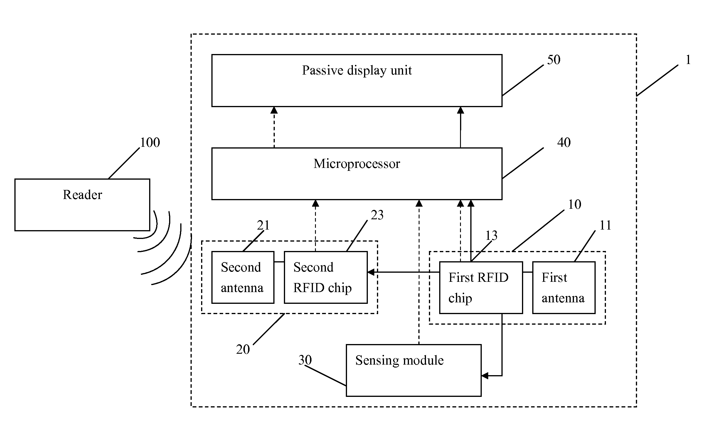
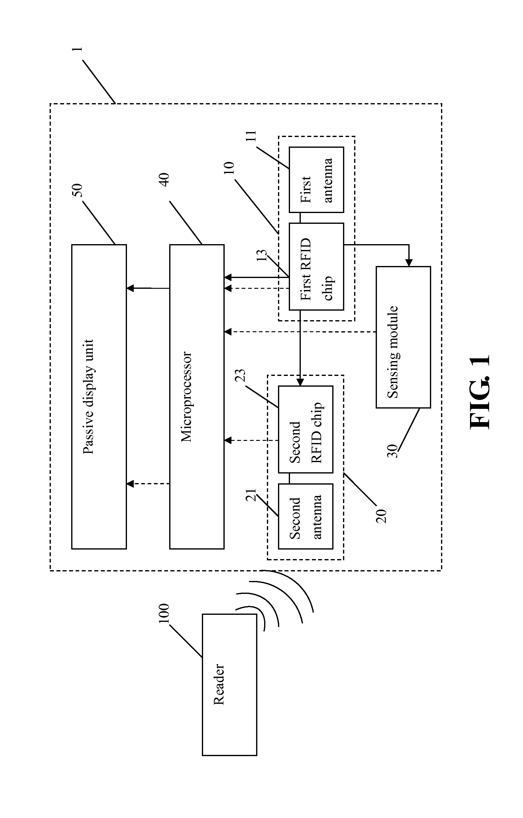
The present invention uses two RFIDs to power a passive display without needing an external power source. Additionally, the sensing module adjusts the brightness and contrast of the display to improve the display effect. This saves time and increases efficiency during stock take.

Problems solved by technology

Owing to the simple architecture of the RFID, usually only comprising the antenna and the RFID chip, the malfunction of reading data possibly occurs when the various goods of the same sort are scanned to read the stored data.
Or, it sometimes causes the problem of repeatedly reading data.
Additionally, the conventional RFID needs the server and specific management such that the operator can not instantly judge whether the read data is correct.

Method used


Image

  • Radio frequency identification display device
  • Radio frequency identification display device

Examples


Embodiment Construction

[0012]The present invention may be embodied in various forms and the details of the preferred embodiments of the present invention will be described in the subsequent content with reference to the accompanying drawings. The drawings (not to scale) show and depict only the preferred embodiments of the invention and shall not be considered as limitations to the scope of the present invention. Modifications of the shape of the present invention shall too be considered to be within the spirit of the present invention.

[0013]Please refer to FIG. 1, which shows a RFID display device according to one embodiment of the present invention. As shown in FIG. 1, the RFID display device 1 of the present invention comprises a first RFID 10, a second RFID 20, a sensing module 30, a microprocessor 40 and a passive display unit 50. Specifically, the first RFID 10 comprises a first antenna 11 and a first RFID chip 13 connected to the first antenna 11. The first antenna 11 receives electromagnetic wave ...


PUM


Abstract

A radio frequency identification (RFID) display device includes a microprocessor, a first RFID, a second RFID, a sensing module and a passive display unit. The first RFID stores a first RFID data and receives electromagnetic wave emitted from a reader for supply power. The second RFID stores a second RFID data. The first RFID data and the second RFID data are transferred to the microprocessor when the electromagnetic wave is received. The sensing module senses an external environment and generates an environmental sensing signal transferred to the microprocessor. The microprocessor generates a display driving signal to drive the passive display unit based on the received data so as to display the RFID data onto the passive display unit. The microprocessor further adjusts the brightness and the contrast of the passive display unit to achieve better display effect, thereby effectively saving the time of stock take.

Description

BACKGROUND OF THE INVENTION[0001]1. Field of the Invention[0002]The present invention generally relates to a radio frequency identification (RFID) display device, and more specifically to a RFID display device employing two RFIDs for supplying power and storing data so as to avoid the reading malfunction and improve the safety of the operation.[0003]2. The Prior Arts[0004]With the progress of the technologies in RFID, the current RFIDs can store more data and are broadly used much more than conventional bar code machines, like logistics, storehouse, declaration at customs, electronic purse, and so on.[0005]Owing to the simple architecture of the RFID, usually only comprising the antenna and the RFID chip, the malfunction of reading data possibly occurs when the various goods of the same sort are scanned to read the stored data. Or, it sometimes causes the problem of repeatedly reading data. Additionally, the conventional RFID needs the server and specific management such that the op...

Claims


Application Information

Patent Timeline
IPC IPC(8): G06K7/10
CPCG06K7/10366G06K19/0717G06K19/07707G06K19/07766
Inventor LIU, TAI-HWASUNG, YI-CHUN
Owner LIU TAI HWA
Learn More