Unlock instant, AI-driven research and patent intelligence for your innovation.

System and method for energy recovery

a technology of energy recovery and energy recovery, applied in the direction of locomotives, machines/engines, transportation and packaging, etc., can solve the problems of heat loss through various other components of vehicles, heat loss associated with exhaust, waste of heat extracted from the intake air in the intercooler and the aftercooler,

Inactive Publication Date: 2015-04-16
ELECTRO-MOTIVE DIESEL
View PDF2 Cites 2 Cited by
  • Summary
  • Abstract
  • Description
  • Claims
  • Application Information

AI Technical Summary

Benefits of technology

The present patent is about an energy recovery system for vehicles. It includes a thermoelectric module that uses waste heat from the vehicle's heat source to generate power. A low temperature heat source is also used, and the temperature difference between the two generates power. A controller is used to select the low temperature heat source based on the temperature difference and the vehicle's operating parameters. The technical effect of this system is the recovery of waste heat from the vehicle's heat source and a higher efficiency of energy utilization.

Problems solved by technology

Consequently, a heat associated with the exhaust may be wasted.
Further, heat extracted from the intake air in the intercooler and the aftercooler may also be wasted.
Heat may also be lost through various other components of the vehicles, for example, but not limited to, a dynamic brake grid, a radiator etc.
Therefore, an efficiency of the vehicles may get reduced.

Method used


Image

  • System and method for energy recovery
  • System and method for energy recovery
  • System and method for energy recovery

Examples


Embodiment Construction

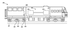
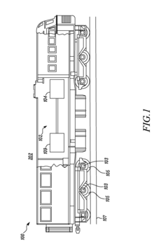
[0013]Wherever possible, the same reference numbers will be used throughout the drawings to refer to the same or the like parts. Referring to FIG. 1, an exemplary vehicle 100 is illustrated. Specifically, the vehicle 100 is a locomotive. Alternately, the vehicle 100 may be an electric multiple unit, a trolleybus, a tram, or the like.

[0014]The vehicle 100 includes a power source 102 (shown schematically). In an embodiment, the power source 102 may include an engine 104 coupled to an electric generator 109. The engine 104 may also provide power to other components of the vehicle 100. The engine 104 may be an internal combustion engine or a gas turbine. In a specific embodiment, the engine 104 may be a diesel engine. The electric generator 109 may provide power to various electric equipment of the vehicle 100 including a vehicle drive system (shown schematically in later figures) and an auxiliary system (shown schematically in later figures) of the vehicle 100. The vehicle drive system...


PUM


Abstract

The present disclosure relates to a energy recovery system for a vehicle. The waste recovery system includes a thermoelectric module which is interfaced with a heat source of the vehicle. The heat source generates waste heat. Further, the waste heat provides a high temperature heat source for the thermoelectric module. A low temperature heat source is also interfaced with the thermoelectric module. A temperature difference between the high temperature heat source and the low temperature heat source generates thermoelectric power. A controller is configured to select the low temperature heat source based on at least one of the temperature difference associated with the thermoelectric module, and an operating parameter of the vehicle.

Description

TECHNICAL FIELD[0001]The present disclosure relates to a system and a method for energy recovery, and more specifically to a system and a method for generating electric power from waste heat in a vehicle.BACKGROUND[0002]Vehicles powered by an engine are well known in the art. In some cases, the engine may be coupled with an electric generator. The electric generator may provide power to various electrical equipment of the vehicle. The engine may also provide power directly to one or more components of the vehicle.[0003]The engine is provided with an intake air for combustion with a fuel. The engine generates an exhaust as a byproduct of combustion. In some engines, the exhaust may provide power to one or more turbochargers in order to compress the intake air in one or more stages before supplying the intake air to the engine. Due to compression, an intercooler and an aftercooler may be provided to cool the intake air after each stage of compression.[0004]The exhaust may be discharge...

Claims


Application Information

Patent Timeline
Patent Type & Authority Applications(United States)
IPC IPC(8): H01L35/30H10N10/13
CPCH01L35/30B61C5/00F01N5/025Y02T10/12H10N10/13
Inventor LAMBA, HARINDER S.
Owner ELECTRO-MOTIVE DIESEL