Quick lock kettlebell handle

a kettlebell handle and lock technology, applied in the field of exercise devices, can solve the problems of prohibitively high price of owning a useful set of weights with the weights available in various sizes, and achieve the effect of quick releasable handles

Inactive Publication Date: 2015-04-16
ODNEAL JOSEPH +1
View PDF0 Cites 40 Cited by
  • Summary
  • Abstract
  • Description
  • Claims
  • Application Information

AI Technical Summary

Benefits of technology

[0008]In view of the shortcomings of the prior art, it is the object of this invention to provide a quickly releasable handle that can mount and detach from commercially available dumbbells. It is also desirable to have the

Problems solved by technology

However, owning a useful set of weights with the weights available in various sizes can be prohibitively expensive.
However, kettlebells have a gen

Method used


Image

  • Quick lock kettlebell handle
  • Quick lock kettlebell handle
  • Quick lock kettlebell handle

Examples


Embodiment Construction

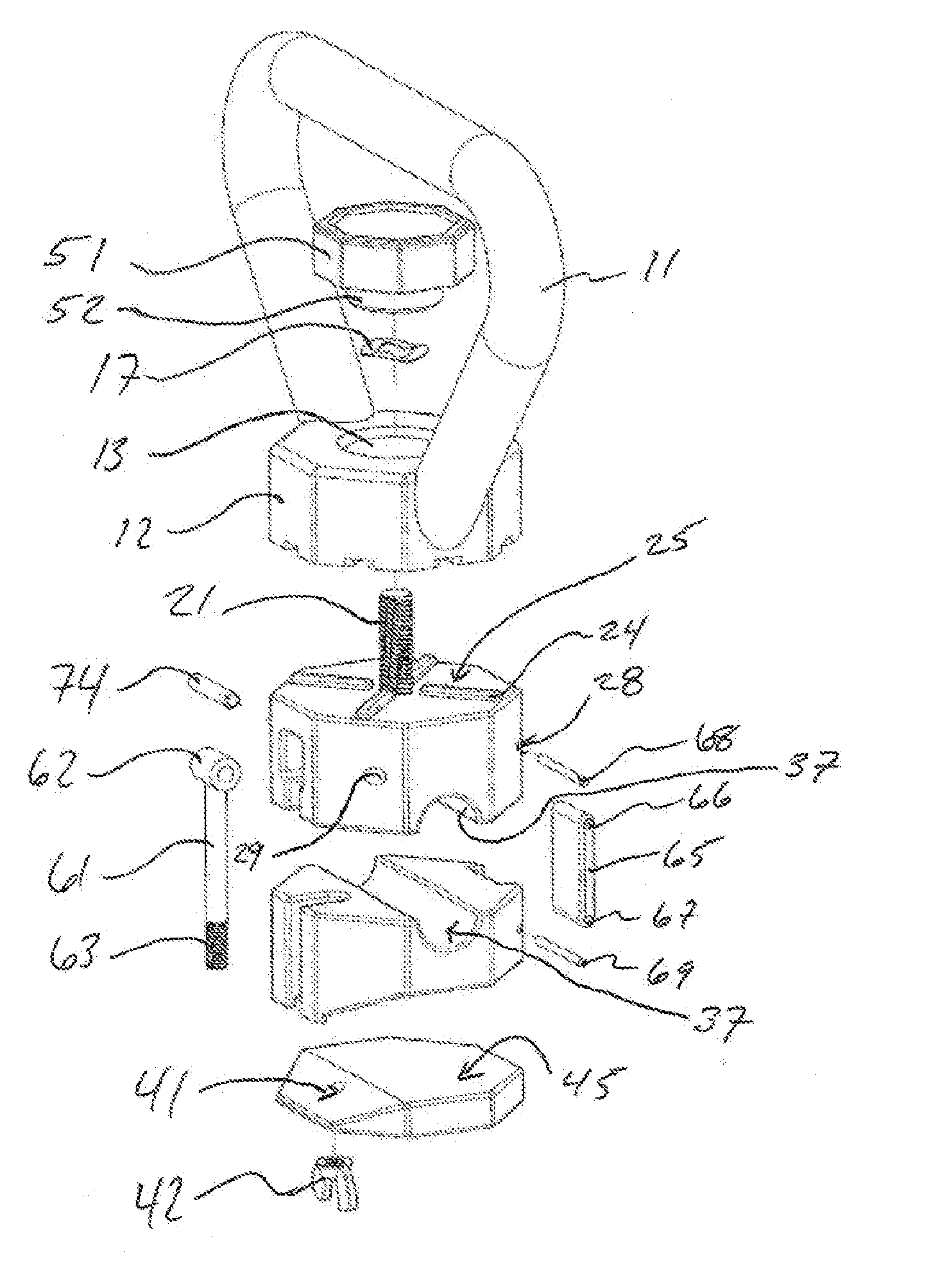
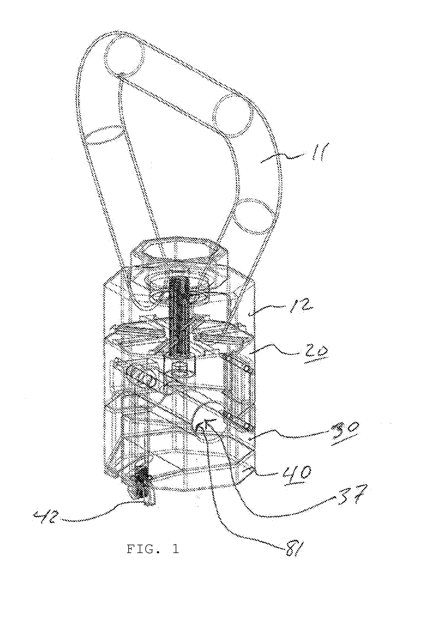
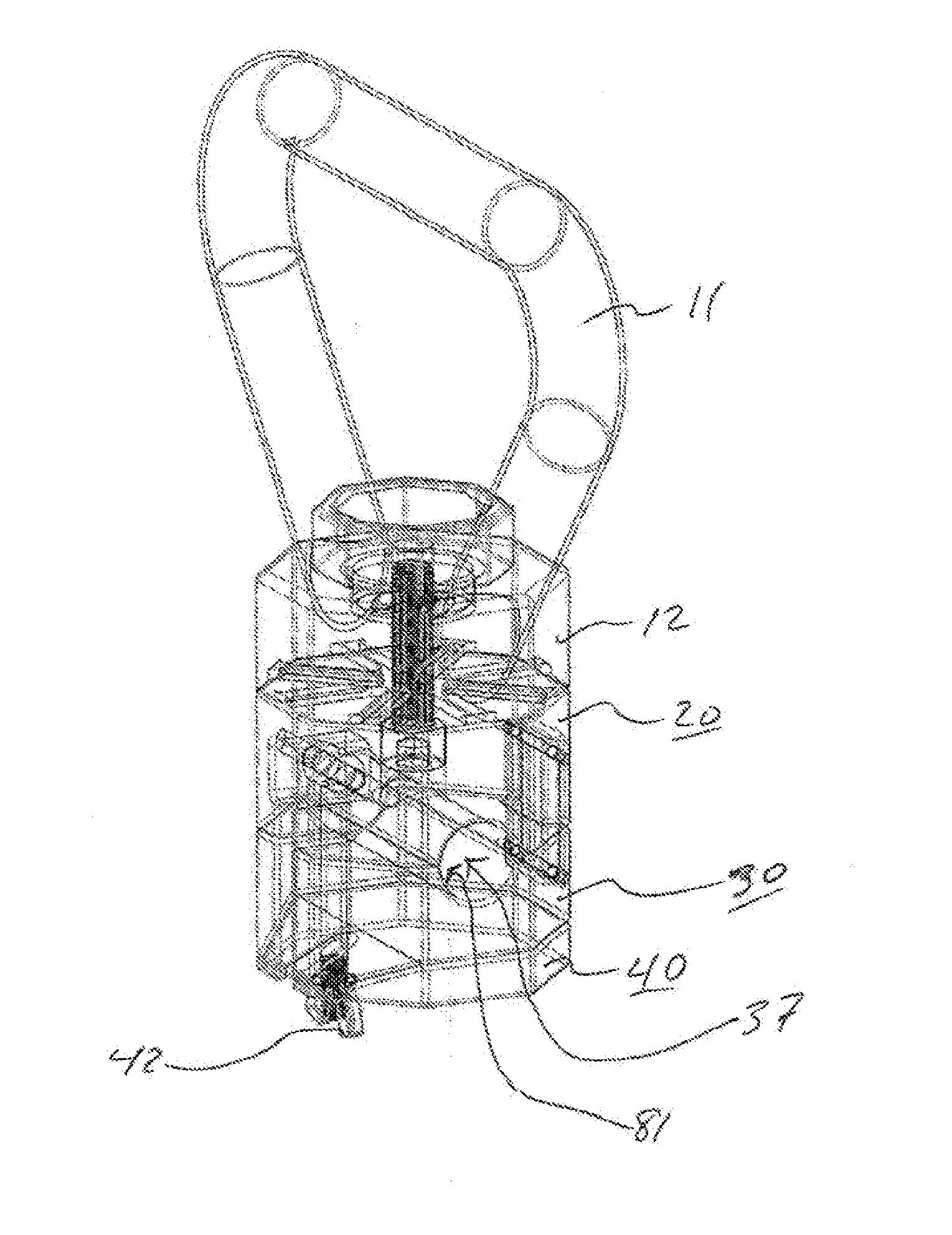
[0027]Referring now to the drawings wherein the showings are for purposes of illustrating a preferred embodiment of the present invention and not for purposes of limiting the same, FIG. 1 shows an exploded line drawing of a preferred embodiment. There are four main components comprising a handle 10, an upper body 20, a lower body 30, and a bottom cap 40. The handle 10 has a handle portion 11 comprising a loop structure that attaches to the handle body 12 in two locations (though different designs could comprise more or fewer attachment points). The handle body 12 further comprises a handle body receiver 13 which is designed to mate with a threaded top cap 51 at a threaded top cap projection 52. The threaded top cap projection 52 is cylindrical and projects down into the handle body receiver 13 which has a slightly larger diameter so that the threaded top cap 51 can freely turn. The threaded top projection 52 aids alignment and stability of the attachment of the handle 10 to the uppe...


PUM

PropertyMeasurementUnit
Weightaaaaaaaaaa
Sizeaaaaaaaaaa
Shapeaaaaaaaaaa

Abstract

The present invention relates to a new handle for adapting kettlebell weights and for new modes of lifting weights.

Description

CROSS-REFERENCE TO RELATED APPLICATION[0001]Continuation-in-part of United States pending patent application Ser. No. 13 / 232,973 dated Sep. 14, 2010 and claiming priority to United States provisional application No. 61 / 382,691 dated Sep. 14, 2010 the contents of which are hereby incorporated by reference.BACKGROUND[0002]The present invention relates to exercise devices and methods of use thereof. In particular, the invention relates to a handle for converting standard weights into kettlebell weights.[0003]Mixed martial arts have become very popular and have ushered in a new wave of work out routines that are taken from the past. Today martial artists use historical but proven techniques to improve strength and performance. A wide variety of weight training techniques are known, including the fixed or variable weight type of exercise machines, cast dumbbells, and the free weight / bar combination. However, owning a useful set of weights with the weights available in various sizes can b...

Claims


Application Information

Patent Timeline
IPC IPC(8): A63B21/072B22D17/00B22D25/02
CPCA63B21/0728A63B21/0726B22D25/02B22D17/00A63B21/072A63B21/4035A63B21/0722Y10T29/49
Inventor ODNEAL, JOSEPHSIMPSON, QUINN
Owner ODNEAL JOSEPH
Why Eureka
Try Eureka