Container with twist-off closure

a technology of twist-off closure and container, which is applied in the field of containers, can solve the problems that the steel closure cannot be used in this arrangement, and achieve the effects of reducing the opening torque, and reducing the number of lubricants

Active Publication Date: 2015-04-23
CROWN PACKAGING TECH
View PDF10 Cites 7 Cited by
  • Summary
  • Abstract
  • Description
  • Claims
  • Application Information

AI Technical Summary

Benefits of technology

[0014]The torque required to open a container made in accordance with the invention is considerably less than typically required to open a threaded container. For example, the opening torque for a 51 mm closure has been reduced from about 3.4 Nm to on

Problems solved by technology

A steel closure cannot be used in this arrangement since ste

Method used


Image

  • Container with twist-off closure
  • Container with twist-off closure
  • Container with twist-off closure

Examples


first embodiment

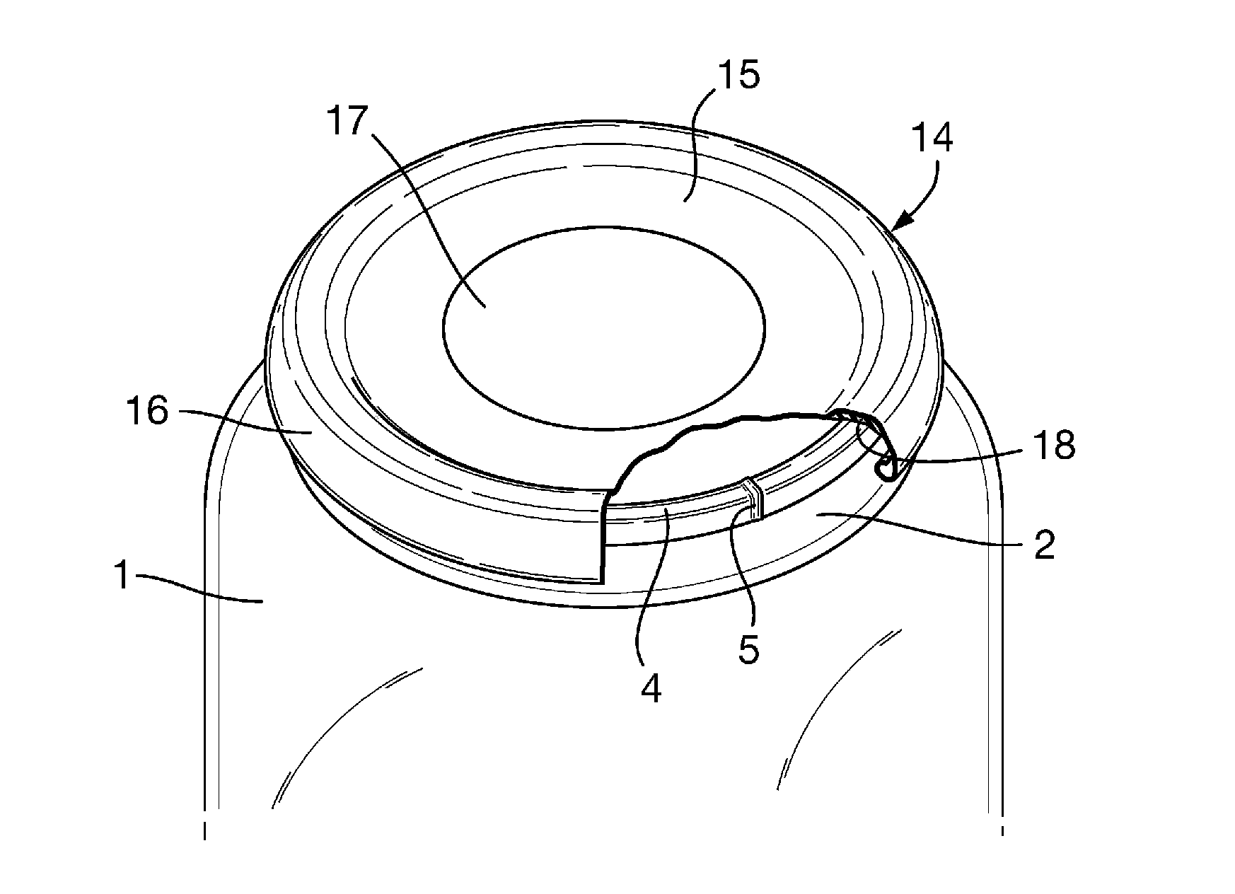
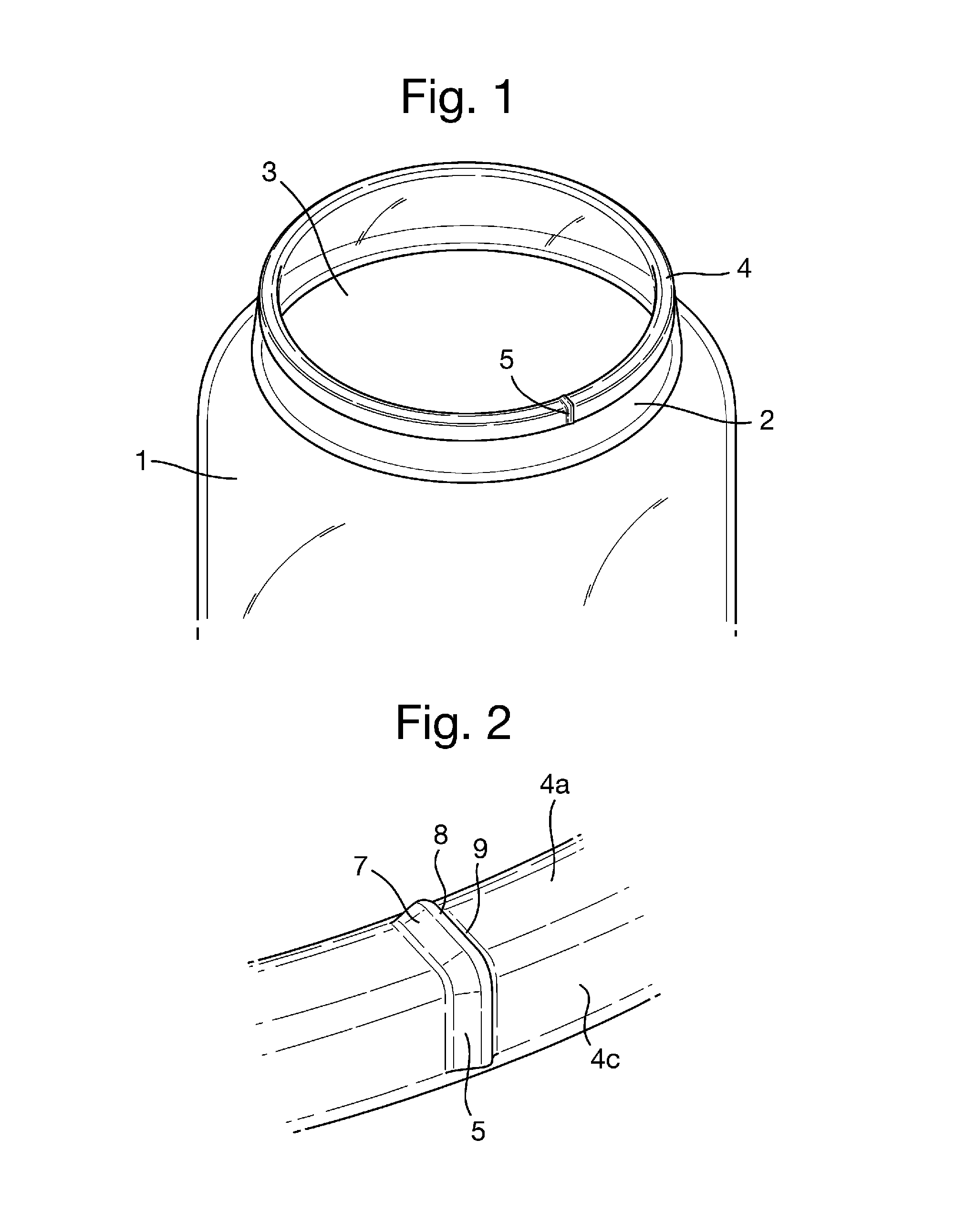
[0030]A first embodiment, shown in FIGS. 1 to 3, 7 and 9, comprises a glass container body 1 having a neck 2 with a circular opening 3 surrounded by an upper rim which defines an annular sealing surface 4 which is provided primarily by the generally flat top edge face 4a of the neck and also by the upper parts of the inner and outer surfaces 4b, 4c of the neck. A venting feature comprising a localised discontinuity in the surface 4 is provided by a small protrusion 5 which extends generally radially across the surface 4 so as to extend downwardly beyond the reach of the annular layer of sealing compound when a closure is fitted as best seen in FIG. 9 so that it extends continuously from the interior of the container body to the exterior of the container body. The protrusion has a curved circumferential profile generally comprising an upslope 7, a curved top 8 and a downslope 9. The upslope 7 is inclined to the surface 4 at an angle θ which is less than 30°. The angle θ is on the tra...

second embodiment

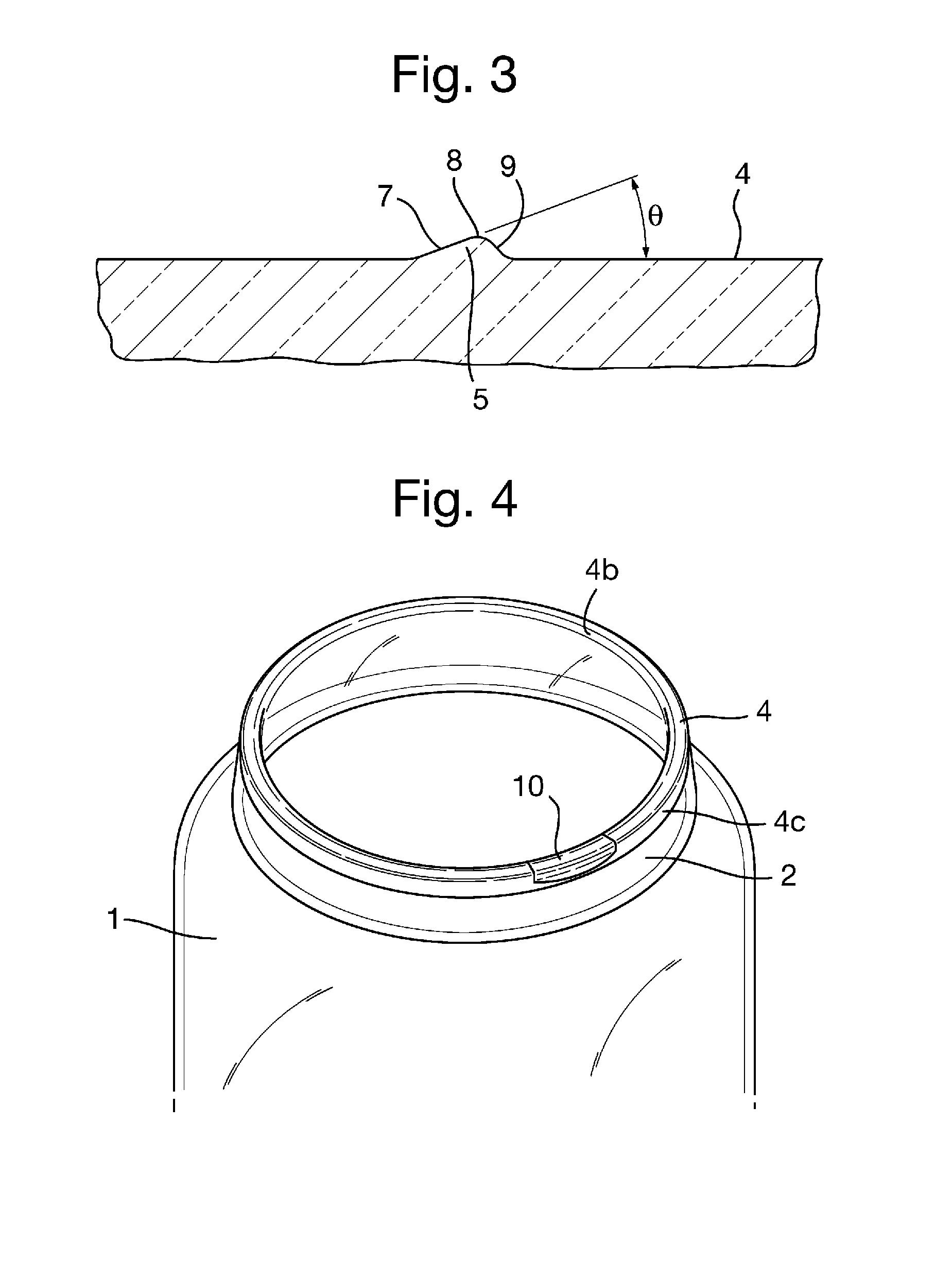
[0032]In a second embodiment, shown in FIGS. 4 to 6 and 8, the discontinuity is provided by a shallow recess or groove 10 having a continuously curved surface 11. The recess again extends radially across the sealing surface 4 and partially down the inner and outer surfaces 4b, 4c of the neck 2 so that it extends continuously from the interior of the container body to the exterior of the container body.

[0033]The shallow recess 10 has a circumferential length of about 5 mm and a depth of about 0.2 mm. In a preferred embodiment the profile of the recess is part circular with a radius of about 16 mm. Thus, the recess in the annular sealing surface 4 is part cylindrical.

[0034]A variant of the second embodiment is shown in FIGS. 12 to 14. In this embodiment, the container body is in the form of a glass tumbler having an annular bead 20 around its upper end. One or more shallow recesses 10 are formed in the radial outer face of the bead. The recess in this variant has a depth of about 0.4 ...


PUM


Abstract

A container comprises a releasable metal closure 14 formed with an end wall 15 and a depending skirt 16 and having an annular layer 18 of sealing compound provided on the inside of the end wall adjacent the skirt and a container body 1 comprising a neck 2 with an annular sealing surface 4 surrounding a circular opening and adapted to seal against the annular layer of sealing compound over an annular sealing interface in the closed position of the closure on the container body. The container body 1 and the closure 14 are formed with no mechanical means for coupling them together to form or maintain a seal therebetween and the seal is provided by a partial vacuum formed in the container during processing. The annular sealing surface 4 of the container body 1 is formed with a localised protrusion 5 or recess 10 which provides a discontinuity in the annular sealing interface, whereby relative rotation of the closure 14 and container body 1 from the closed position creates a venting path from the interior of the container body to the exterior so that the seal is broken and the closure is released.

Description

TECHNICAL FIELD[0001]The invention relates to a container comprising a glass container body and a releasable metal closure containing an annular layer of sealing compound.BACKGROUND ART[0002]Containers are well known in which a metal, releasable cap closure Traditionally, the cap is screw fitted onto the body such that the upper surface of the neck of the container seals against the layer of sealing compound. Filling speeds for such containers are generally up to about 500 containers per minute.[0003]Because of the time taken to fit a screw closure during production, a modified arrangement has been developed in which a closure is formed with sealing compound moulded to the outer part of the closure end wall and to the inside of the closure sidewall or skirt. This kind of closure may be push fitted onto a screw threaded container during production of a filled container. Filling speeds for such containers may be up to about 1,000 containers per minute. The screw threads of the body di...

Claims


Application Information

Patent Timeline
IPC IPC(8): B65D41/04B65D1/10
CPCB65D1/10B65D41/0428B65D1/0253B65D41/165B65D51/1688B65D2543/00546
Inventor MCGIRR, LAURA JANENICHOLIS, ANNE ELIZABETHRAMSEY, CHRISTOPHER PAUL
Owner CROWN PACKAGING TECH
Why Eureka
Try Eureka