
Retractable projection screen

Inactive Publication Date: 2015-04-23
VASSARDS JEAN MARC
View PDF12 Cites 5 Cited by
  • Summary
  • Abstract
  • Description
  • Claims
  • Application Information

AI Technical Summary

Benefits of technology

The present invention is a mechanical device that allows for the screen to be hidden behind art or pictures. The device is simple, reliable, and cost-effective. It can be adjusted to different screen sizes and can be extended or retracted. The screen is always stretched without folds and can be moved without losing its shape. The device can also have built-in speakers, and the screen can have micro-perforations to improve sound diffusion.

Problems solved by technology

This projection screen is generally mounted on a wall and occupies a large space that prohibits installing any other setting in the place of this screen.
When it is not used as a projection screen, it shows a white surface, surrounded or not by a black frame, which is neither aesthetic nor pleasant to the eye in a living room.
However, these constraints limit the development possibilities of home cinema and hold back in particular potential users who have no specific room to dedicate to cinema.
This solution is not satisfactory, both in terms of picture quality, since the screen is not stretched laterally and distorts the picture, and in terms of practicality and aesthetics in a living room.
This solution is not satisfactory as the fabric is folded in its retracted position, the mechanism is complex and cumbersome on the back of the picture, which in most cases imposes letting said casing into the wall, entailing additional work and expenses.
Moreover, this solution is restricted to one screen size and one screen type, and does not allow considering different screen sizes according to the format of the projection, neither different reflective qualities for the screen.
However, this fabric cannot provide a projected image of high quality as its free ends are floating, not held and can generate distortions of the projected image.
However, the implementation of this solution is complex, costly and not reliable.
The addition of the slides leads to extra manufacturing costs and to excess thicknesses in the free edges of the screen that can be prejudicial both to the size and to the integrity of the screen when it is wound on itself.
Moreover, this solution cannot be transposed to a support sheet that circulates between two rollers as nothing is provided to prevent the fabric from shifting transversally with respect to the rollers.

Method used


Image

  • Retractable projection screen
  • Retractable projection screen
  • Retractable projection screen

Examples


Embodiment Construction

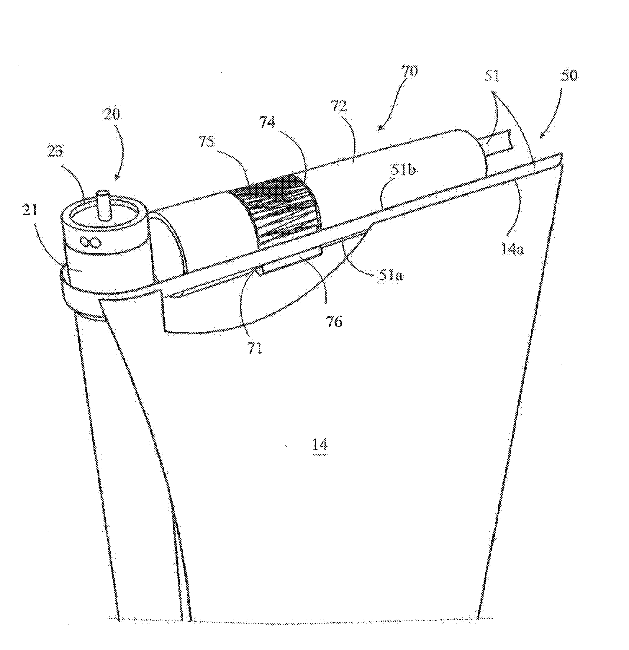
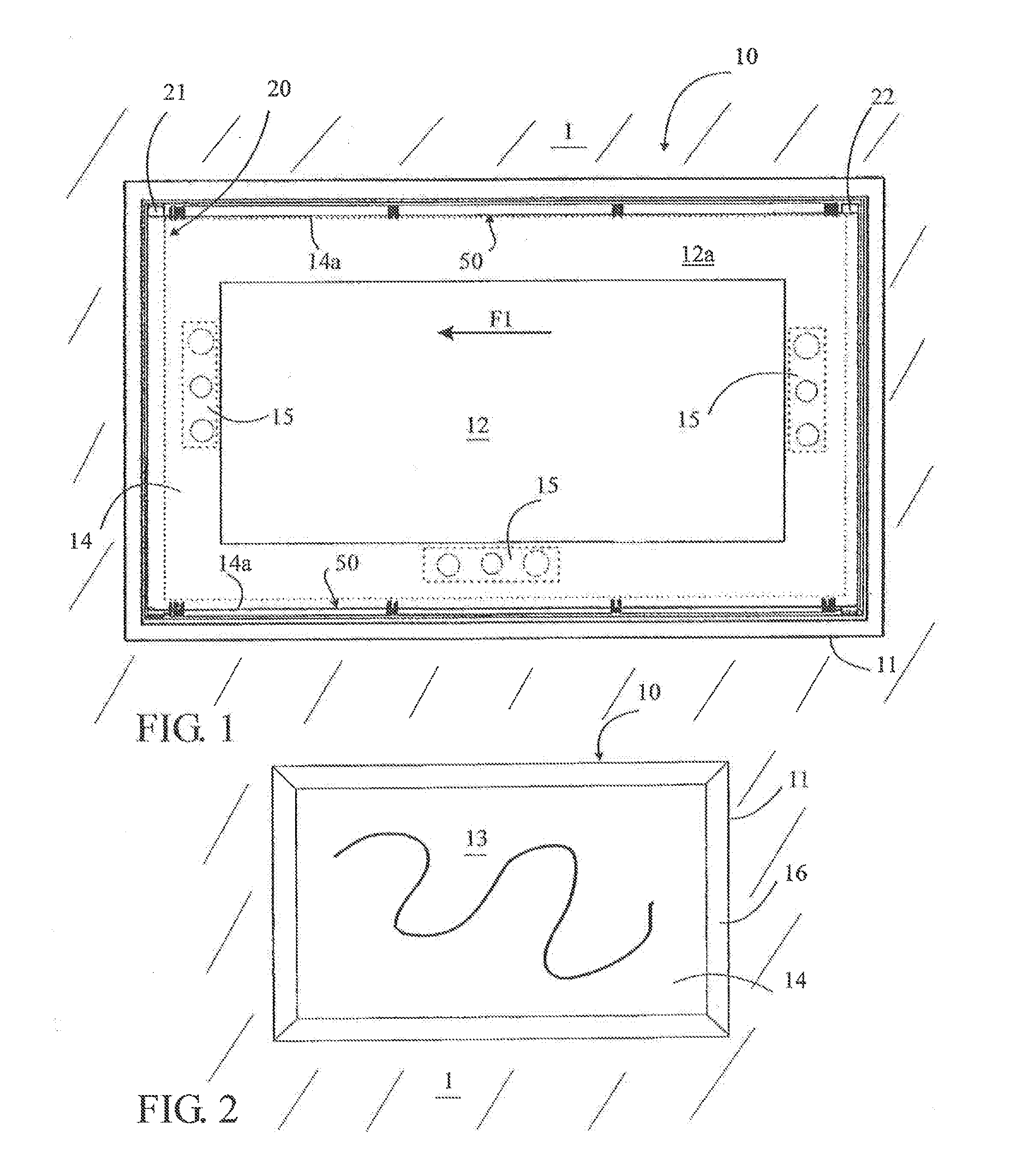
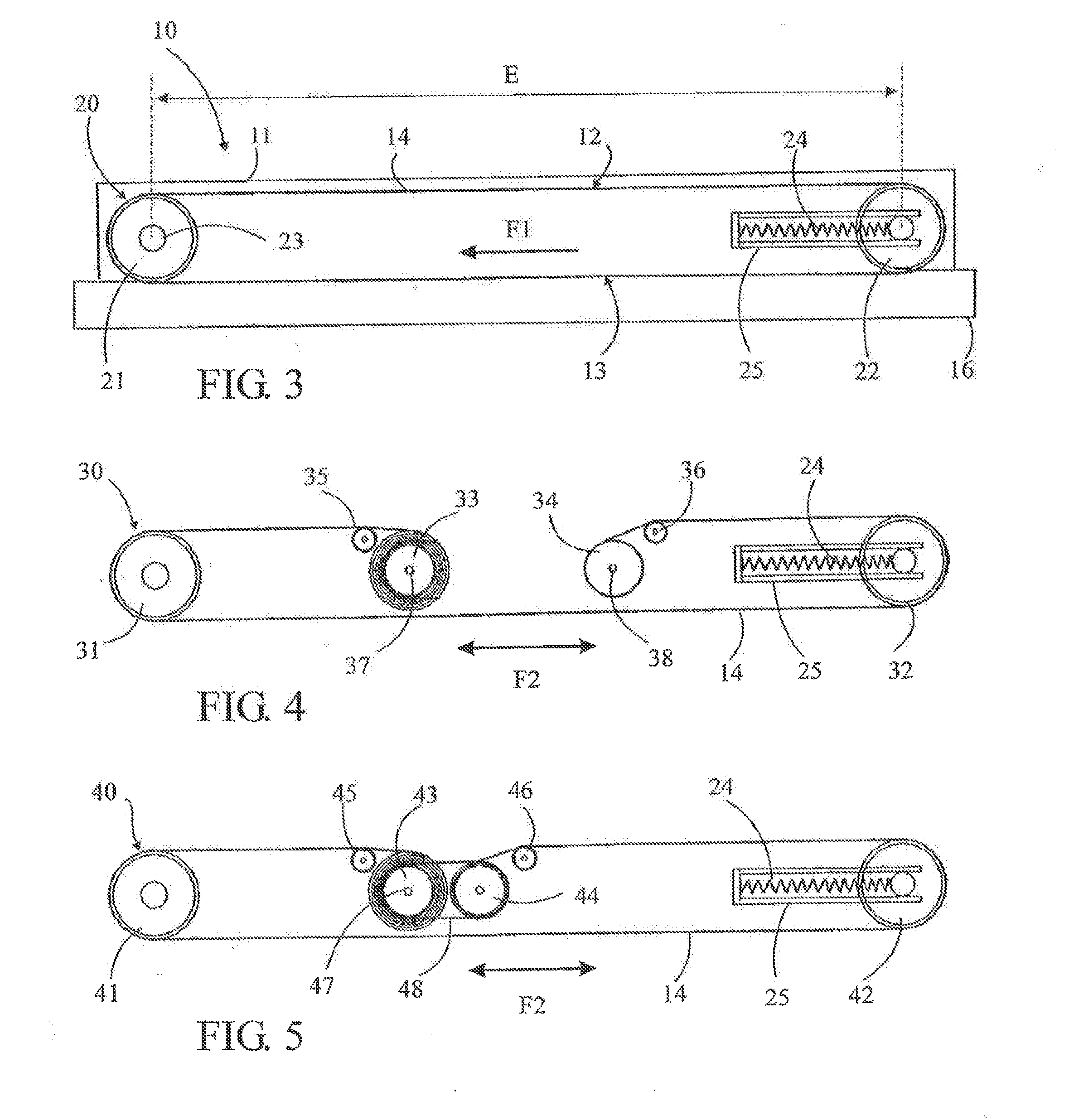
[0037]Referring to FIGS. 1 to 8, the retractable projection screen 10 according to the invention includes at least one casing 11 arranged to be hung on a wall 1, on a carrier structure or similar. In the represented example, this casing 11 is rectangular and the wall 1 is a wail or a partition wall. Of course, this casing 11 can be superimposed on a wall 1 or integrated in a recess arranged for this purpose in said wall 1. It can also be formed by the recess itself. This casing can also be supported by an underframe or similar resting on the floor or on any other surface, in a fixed or rolling manner. In the whole text, the expression “casing 11” includes all these various possibilities. It includes a cover frame 16 arranged around casing 11 to hide the internal mechanism. This cover frame 16 can be made of a commercially available framing or of a frame designed especially for said device, according to the desired aesthetics. This cover frame 16 can be separate or integrated and bel...


PUM


Abstract

A screen device (10) having a casing (10), a projection screen (12) and a setting (13) associated with displacement mechanism (20) for modifying the visible content of the casing. The projection screen (12) and the setting (13) are combined on a unitary support sheet (14) and the displacement mechanism (20) comprise two parallel winding rollers (21, 22) about which the support sheet (14) is wound, and one of the rollers is a driven roller. Stiffening mechanism (50) is associated with the two free edges (14a) of the support sheet (14) for stiffening the free edges in the winding direction of the and to confer a perfect flatness to the sheet over its entire surface area. A guide mechanism (60) is associated with the stiffening mechanism (50) for the free edges (14a) of the support sheet (14).

Description

[0001]This application is a National Stage completion of PCT / FR2013 / 000115 filed Apr. 25, 2013, which claims priority from French patent application serial no. 12 / 53923 filed Apr. 27, 2012.FIELD OF THE INVENTION[0002]The present invention relates to a retractable projection screen device including at least one projection screen and at least one setting superimposed on said projection screen in at least one retracted position of said screen, and displacement means associated respectively with said projection screen and / or with said setting to move at least one of said projection screen or said setting with respect to the other in order to make said projection screen visible in at least one position of use of said screen, said at least one projection screen being carried by a support sheet and said displacement means including at least two parallel winding rollers whereon said support sheet winds up, at least one of said rollers being a motorized driving roller.BACKGROUND OF THE INVEN...

Claims


Application Information

Patent Timeline
IPC IPC(8): G03B21/58G03B21/56
CPCG03B21/565G03B21/58G03B21/56
Inventor MIGGIANO, ROBERT
Owner VASSARDS JEAN MARC
Learn More