
Method for manufacturing an injection device with a bypass channel and tool for this purpose

a bypass channel and injection device technology, applied in the field of manufacturing an injection device with a bypass channel and a tool for this purpose, can solve problems such as contamination of finished products

Active Publication Date: 2022-10-04
GERRESHEIMER REGENSBURG GMBH
View PDF9 Cites 0 Cited by
  • Summary
  • Abstract
  • Description
  • Claims
  • Application Information

AI Technical Summary

Benefits of technology

[0007]An object of the invention is to provide a method for manufacturing an injection device with a bypass channel, which is easy and reliable to handle and reduces the cost per manufactured injection device.
[0009]Furthermore, an object of the invention is to provide a tool for manufacturing an injection device with a bypass channel, with which the bypass channel can be formed in the injection device in a simple, reliable and cost-effective manner.
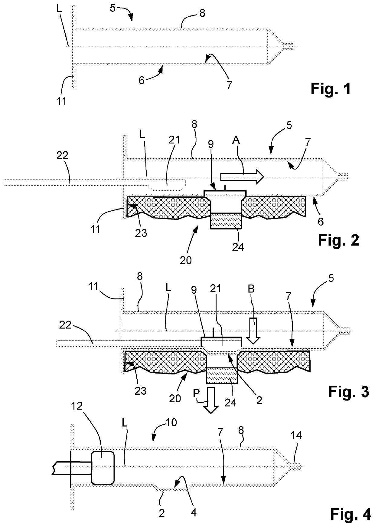
[0012]The inventive method has the advantage that the bypass channel is formed by means of the male die part, e.g. after the injection molding process. By using the male die part cost consuming resources can be saved and in the body of the injection syringe no particles or separations accrue, which would lead to contamination of the finished product.
[0017]In an embodiment of the tool of the invention, the heat source is configured as a contact heat source and / or as a radiant heat source. In a further embodiment of the tool of the invention, the tool has formed a stop for a handle of the preform for positioning of the preform in the tool. This has the advantage that the preform with the partial area to be heated is reproducibly positioned opposite to the heat source of the tool.

Problems solved by technology

By using the male die part cost consuming resources can be saved and in the body of the injection syringe no particles or separations accrue, which would lead to contamination of the finished product.

Method used


Image

  • Method for manufacturing an injection device with a bypass channel and tool for this purpose

Examples


Embodiment Construction

[0025]At the outset, it should be appreciated that like drawing numbers on different drawing views identify identical, or functionally similar, structural elements. It is to be understood that the claims are not limited to the disclosed aspects. The illustrated embodiment for the formation of a bypass channel for an injection device represents only one possible embodiment of how the inventive method can be configured. This is not to be construed as limiting the invention.

[0026]Furthermore, it is understood that this disclosure is not limited to the particular methodology, materials and modifications described and as such may, of course, vary. It is also understood that the terminology used herein is for the purpose of describing particular aspects only, and is not intended to limit the scope of the claims.

[0027]It should be appreciated that the term “substantially” is synonymous with terms such as “nearly,”“very nearly,”“about,”“approximately,”“around,”“bordering on,”“close to,”“ess...


PUM

PropertyMeasurementUnit
pressureaaaaaaaaaa
areaaaaaaaaaaa
temperatureaaaaaaaaaa

Abstract

A tool and a method for manufacturing a bypass in an injection device are disclosed. The preforms of the injection device are inserted into a tool. A partial region of the cylindrical portion is heated by a heat source. The heated partial region of the cylindrical portion is plastically deformed with a male die part of the tool, so that the bypass channel is formed.

Description

CROSS-REFERENCE TO RELATED APPLICATIONS[0001]This non-provisional patent application claims priority under 35 U.S.C. § 119 of German Patent Application No. 10 2018 108 549.4, which was filed in Germany on Apr. 11, 2018, and which is herein incorporated by reference.FIELD OF THE INVENTIONField of the Invention[0002]The invention relates to a method for manufacturing an injection device with a bypass channel. Furthermore, the invention relates to a tool for the method for manufacturing an injection device with a bypass channel.Description of the Background Art[0003]German patent application DE 10 2007 014 281 A1 discloses a method for producing a multi-chamber syringe with a bypass channel. For this purpose, first a preform is produced of a thermoformable plastic with a tubular section. The preform is enclosed in the region in which the bypass channel is to be formed with a mold. The mold has formed a depression in the area of the bypass channel. The preform is heated to a temperature...

Claims


Application Information

Patent Timeline
Patent Type & Authority Patents(United States)
IPC IPC(8): B29C45/14A61M5/31B29C51/10B29L31/00
CPCB29C45/14A61M5/3129B29C51/10A61M2005/3132A61M2207/10B29C2791/006B29L2031/7544B29C55/24B29C67/0022B29C67/0048
Inventor KALB, FRANZLANZL, CHRISTIAN
Owner GERRESHEIMER REGENSBURG GMBH
Learn More