Scour sensor and method of using same

a technology of scour and sensor, applied in the field of sensors, can solve the problems of large amount of effort expended in the research and development of scour monitoring sensors and systems, severe damage to bridges, and inability to detect scour, so as to reduce the amount of information/data, increase the usefulness of the sensor, and reduce the power required to operate the sensor.

Inactive Publication Date: 2015-04-21
THE BOARD OF TRUSTEES OF THE UNIV OF ILLINOIS
View PDF8 Cites 1 Cited by
  • Summary
  • Abstract
  • Description
  • Claims
  • Application Information

AI Technical Summary

Benefits of technology

[0010]In one embodiment, the present invention provides a simple, reliable and cost effective scour monitoring system that is easily mass produced which will have a tremendous impact on the state of health of our bridges. Mass production and cost efficiency paves the way for rapid distribution to highway agencies and ensures safety. Furthermore, it assists the highway officials for scheduling periodical maintenance programs and circumvents costly repairs and bridge replacements as well as emergency road closures. These and other advantages of the embodiments of the invention, as well as additional inventive features, will be apparent from the description of the invention provided herein.
[0016]Further yet, embodiments of the present invention may use only a single sensor element associated with the elongated rod. This reduces the amount information / data that must be analyzed as well as reduces the power required to operate the sensor which increases the usefulness of the sensor in remote locations.

Problems solved by technology

Scour is considered one of the major causes of highway bridge failures in the United States.
During floods, erosion of the foundation materials around and below the bridge piers causes structural instability.
If local scour is not identified in time, the structural integrity of the foundation progressively deteriorates and leads to severe damage and collapse of the bridge.
The 1987 catastrophic collapse of the Schoharie Creek Bridge in New York State due to scour was one of the most severe bridge failures in the United States.
A great amount of effort has been expended for the research and development of scour monitoring sensors and systems.
Applicability of the existing methodologies however has been limited considering issues pertaining to the complexity and cost effectiveness, resolution, capability for providing repeated and reliable information, installation, and rigor in data retrieval and processing.
However, their applicability for monitoring the scour event in real time has been limited and both techniques involve rigorous data processing and interpretation schemes.
The information provided by battery operated devices including those based on neutral buoyancy of seismic transducers are crude and, in general, these devices have limited active lives.
However, it is not possible to reset these devices for reuse and issues pertaining to binding and installations have hindered their usage.
Techniques based on TDR either use sacrificial sensors that break off during scouring events or solely depend on the impedance mismatch and not practical for real applications involving various types of sedimentations.
Attenuation and pulse dispersion errors due to length of electrical cables as well as probe length limitations are amongst other deficiencies of these systems.
Moreover, these multi-sensor arrangements are expensive since they require sophisticated multi-channel data acquisition and interpretation techniques.
Therefore, none of the currently available scour monitoring techniques possesses the necessary attributes for widespread deployment in scour critical bridges.
In addition, the sensor has to survive many floods and operate maintenance-free over a long period of time.
Not withstanding the difficulty of determining scour, it can also be difficult to determine the subgrade modulus of the river bed, or the subgrade modulus for any soil or material for that matter, without unduly disturbing the material or affecting the soil or material once it has been placed in a desired location such as at a construction site.

Method used


Image

  • Scour sensor and method of using same
  • Scour sensor and method of using same
  • Scour sensor and method of using same

Examples


Embodiment Construction

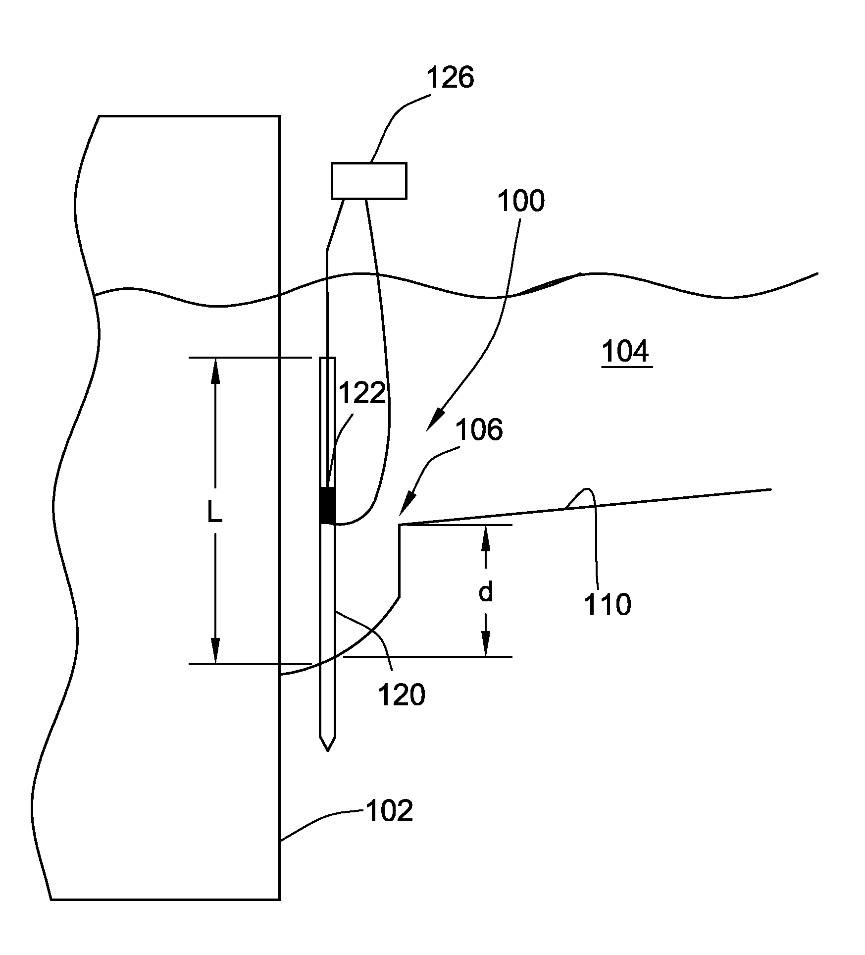
[0060]FIG. 1 illustrates a schematic representation of a scour sensor 100 according to an embodiment of the present invention installed proximate a structure 102 formed in a body of water 104. The scour sensor 100 monitors the depth (d) of scour 106 proximate structure 102. It should be noted that the depth (d) could actually be a measure of a height of deposition of material proximate the structure 102 and not necessarily a depth of removal of material depending on the type of scour that is occurring. Typically, the depth (d) of scour 106 is measured from the bed 110 of the body water 104. Thus, scour is the change in the amount of depth (plus or minus) that the scour sensor 100 is embedded into the bed 110.

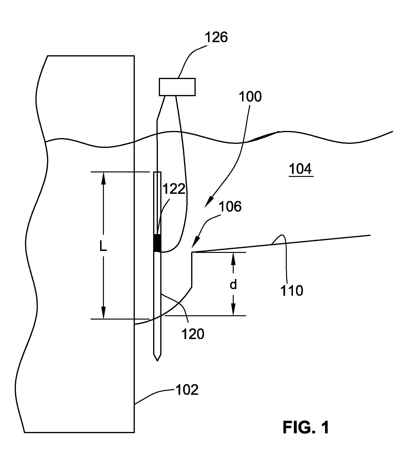
[0061]With supplemental reference to FIG. 2, the sensor 100 generally includes an elongated rod 120 driven into bed 110 of the body of water 104 such that a portion of the rod 120 extends out of and above bed 110 and a portion is embedded into the river bed 110. Due to resistanc...


PUM

PropertyMeasurementUnit
diameteraaaaaaaaaa
diameteraaaaaaaaaa
diameteraaaaaaaaaa

Abstract

A scour sensor and method of detecting scour in the bed of a body of water as well as a sensor and method for determining the subgrade modulus of a subgrade are provided. The scour sensor includes an elongated rod that can be driven into the bed of a body of water such that a portion of the rod is cantilevered from the bed into the water. The rod has a known dynamic characteristic that is variable depending on the amount of the rod that is embedded in the subgrade. In one implementation, the known characteristic is the natural frequency of the rod. The scour sensor further includes a sensor element for monitoring a dynamic characteristic of the rod. Methods of using and calibrating a scour sensor are also provided. Further, the sensor may be used to determine a subgrade modulus of the subgrade.

Description

FIELD OF THE INVENTION[0001]The present invention relates to sensors and more particularly to sensors for monitoring scour of the bed of bodies of water as well as determining the subgrade modulus of a subgrade.BACKGROUND OF THE INVENTION[0002]Scour is considered one of the major causes of highway bridge failures in the United States. It is especially prevalent during floods and periods of rapid river flow activities. During floods, erosion of the foundation materials around and below the bridge piers causes structural instability. This process is dynamic, where erosion takes place near the peak flow rates, and deposition of sediments occur during the descending stages of the flood. If local scour is not identified in time, the structural integrity of the foundation progressively deteriorates and leads to severe damage and collapse of the bridge.[0003]According to the data from the National Bridge Inventory (NBI), 484,546 highway bridges out of an inventory of 590,000 in the United ...

Claims


Application Information

Patent Timeline
Patent Type & Authority Patents(United States)
IPC IPC(8): G01N17/00G01C13/00G01C25/00
CPCG01C13/00G01C25/00
Inventor ANSARI, FARHADIRANMANESH, AMIRHOSSEIN
Owner THE BOARD OF TRUSTEES OF THE UNIV OF ILLINOIS
Why Eureka
Try Eureka