Networked light control system

a networked light control and control system technology, applied in the direction of repeater circuits, line-transmission details, sustainable buildings, etc., can solve the problems of integrating a power line modem system, requiring a costly and cumbersome addition to existing infrastructure in geographical territory, and preventing interference with public safety personnel communications. , the effect of reliably compensating the cost of replacing

Active Publication Date: 2015-11-03
RELUME TECH
View PDF4 Cites 0 Cited by
  • Summary
  • Abstract
  • Description
  • Claims
  • Application Information

AI Technical Summary

Benefits of technology

[0015]The subject invention has the enormous advantage of providing governing organizations in a geographical territory, such as municipalities, counties, and universities, with a simple, reliable, and cost-effective system to replace traditional H.I.D. lamps with LED light assemblies in existing street lights by integrating a remote light control system into their existing radio communication system used for public safety personnel, i.e. without the prohibitive cost of installing an independent and additional radio communication system and the attendant operational disadvantages. A municipality can install and operate the present system at virtually no added cost by using the proven, robust, existing municipal transceivers and repeaters, used for public safety personnel communication, and the existing radio frequencies licensed and reserved to the municipality by the FCC for public safety personnel communication, which are frequencies free of interference. There is no need to make costly changes to existing municipal infrastructure, which is needed to integrate power line modem systems.
[0022]Clearly, the integration of the system with the frequencies reserved for public safety personnel provides enormous cost savings and allows municipalities to install such systems with a four to five year pay back. Additionally, by incorporating the emergency signaling devices, not only is public safety substantially enhanced, but there resides an additional opportunity for revue to offset the initial installation costs. In conclusion, the present system contributes an art-additive to society that reliably and economically improves energy efficiency, reduces energy-related costs, and improves the safety of citizens.

Problems solved by technology

The initial cost of purchasing and installing the LED light assemblies is the only barrier preventing them from doing so.
Existing systems which control street light assemblies in geographical territories have proven useful in reducing the energy consumption of H.I.D. lamps, but are an add-on that is cumbersome and expensive to install and maintain.
As alluded to above, integrating a power line modem system into a municipality or other geographical territory to control and dim street lights including LEDs requires a costly and cumbersome addition to existing infrastructure in the geographical territory.
Signals cannot reliably cross electrical transformer isolated groups if they do not share a common electrical line.
Therefore, the municipality must install a costly modem before the electrical transformer in each group to maintain signal integrity and remotely control the street lights in each group.
However, interconnecting all of the modems to a central system controller remains problematic, i.e. the signaling is only useful in relatively small groups of street lights.
Most municipalities can not afford this huge initial cost.
However, the radio signals are subject to interference from numerous other devices, like portable telephones, microwaves, and video monitors, emitting signals on the same radio frequency, which could easily corrupt the communication.
The range of frequencies available for use by commercially sold mesh systems is very limited, and the signals are often subject to multi-path distortion and severe attenuation from building walls, people, and other objects.
Therefore, mesh radio systems are not reliable enough for the safety critical control of street light assemblies.

Method used


Image

  • Networked light control system
  • Networked light control system
  • Networked light control system

Examples


Embodiment Construction

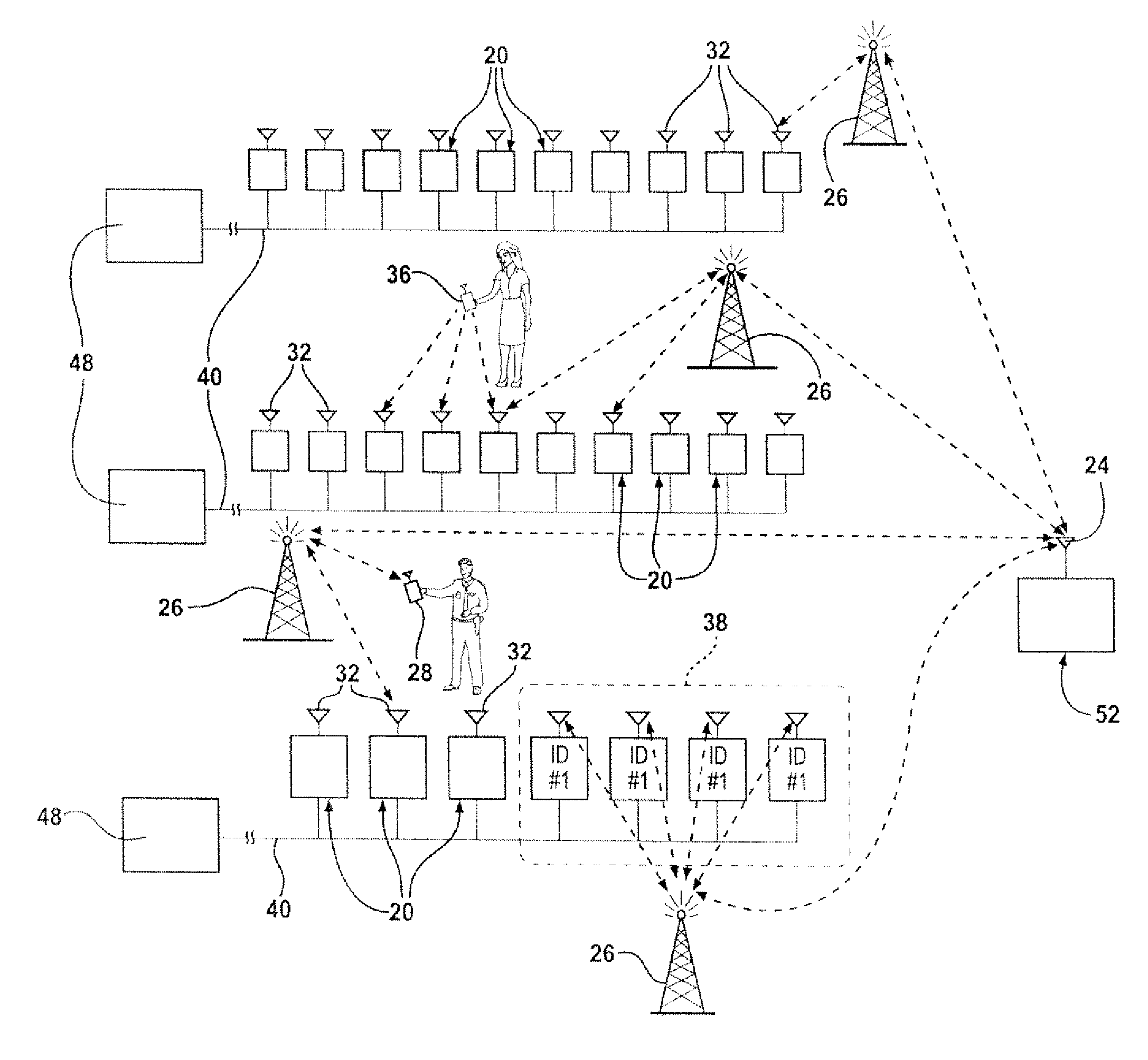
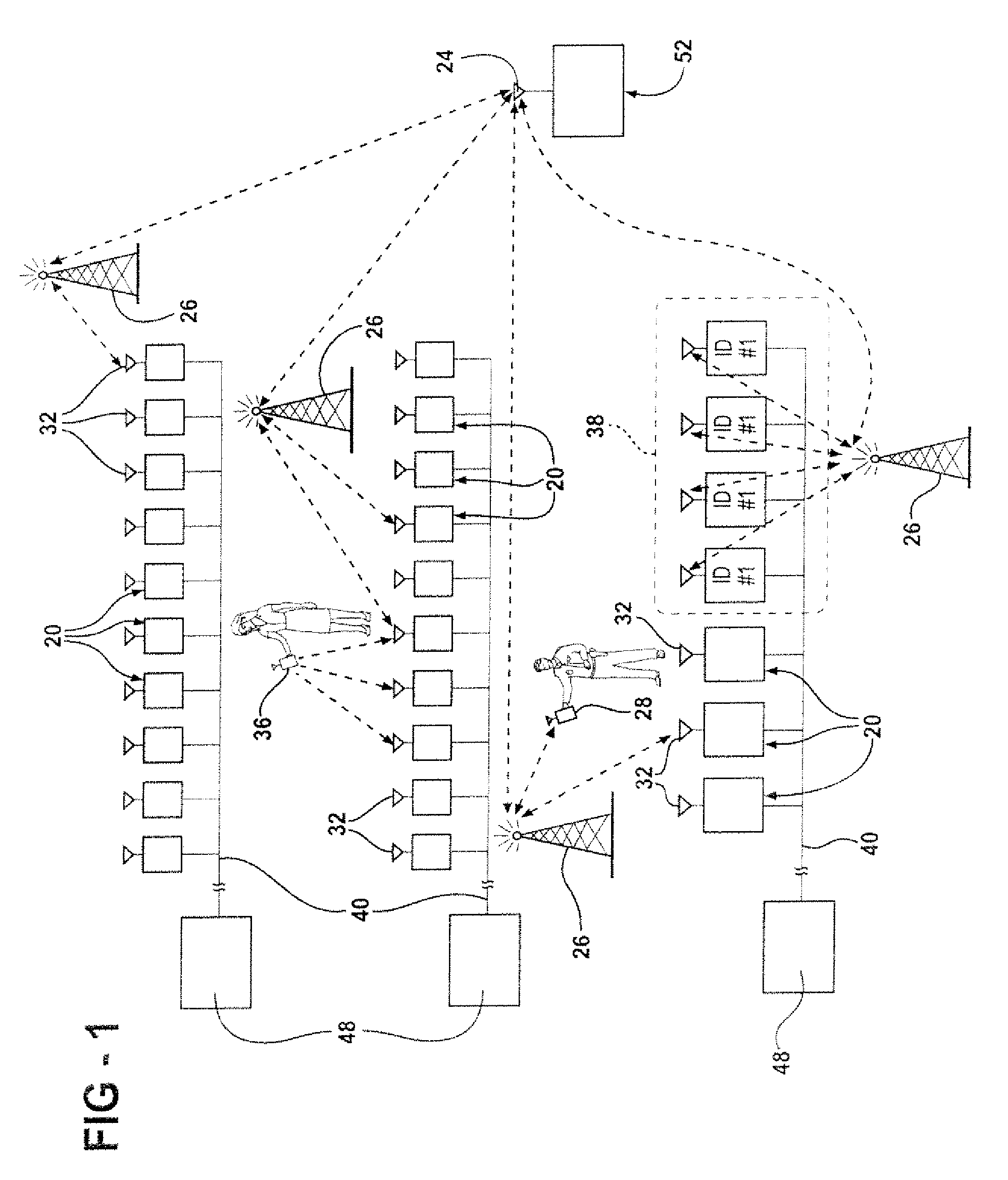
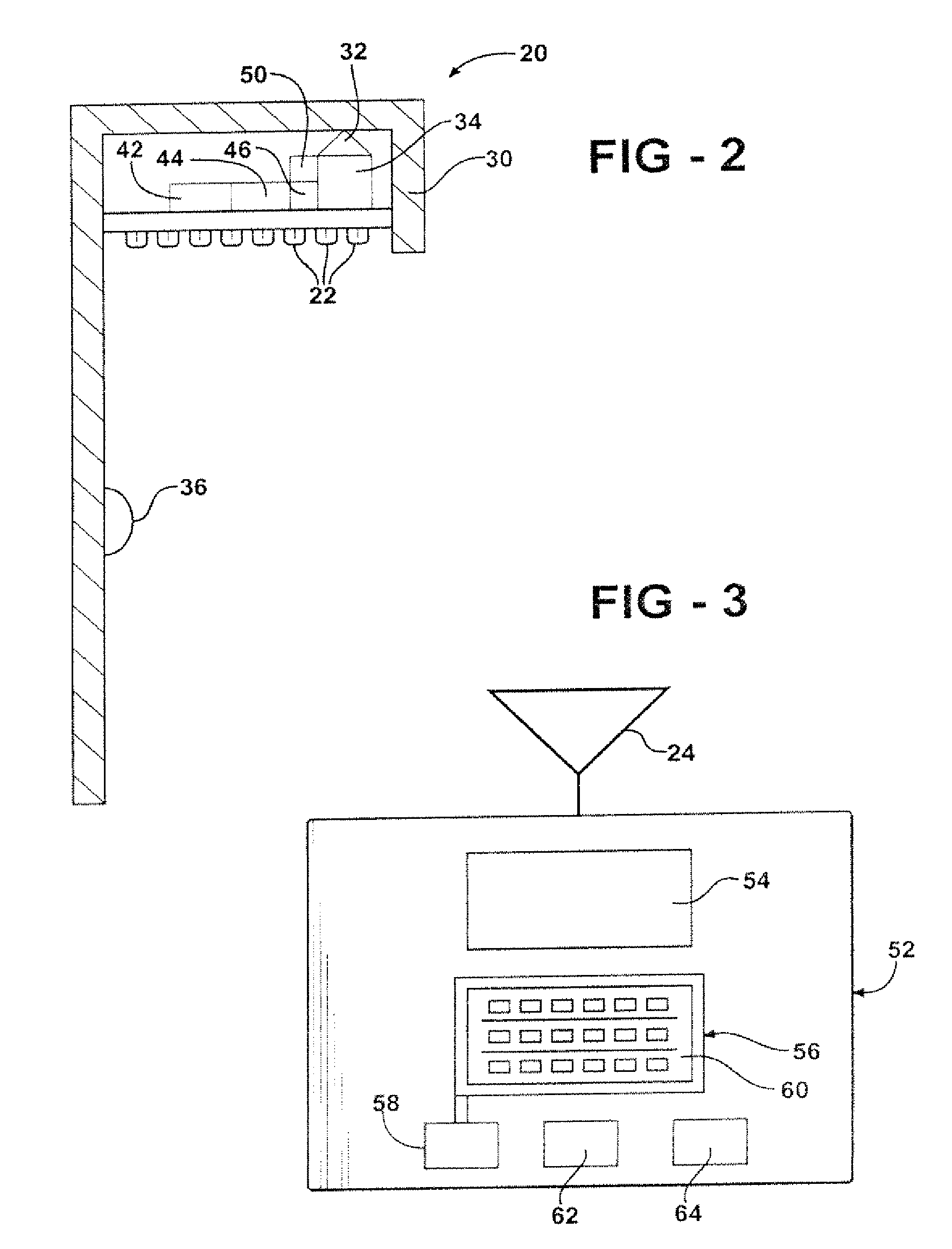
[0027]Referring to the Figures, a networked light control system used to transmit and receive radio signals to and from street light assemblies (20) including LEDs (22) is illustrated as spaced over a geographical territory defined by a central dispatch of public service personnel operating in the geographical territory. The system of the present invention employs existing infrastructure designed for transmitting radio signals on channels of frequencies licensed and reserved by the FCC for public safety communication and other exclusive local uses to control street light assemblies (20) located in a geographical territory such as a municipality, county, or university campus.

[0028]The system employs a central transceiver (24), operated by a governing organization in a geographical territory for transmitting and receiving voice and tones and digital packets on a first radio frequency reserved for public safety personnel. The central transceiver can be an existing transceiver located i...


PUM


Abstract

LED light assemblies (20) are spaced over a geographical territory defined by a central dispatch of public service personnel operating in the geographical territory and are controlled by transmitting digital packets on a first radio frequency reserved for public safety personnel from a central transceiver (24) to repeaters (26) in the geographical territory and re-transmitting the digital packets on a different second frequency reserved for public safety personnel from the repeaters (26) to the light assemblies (20). In turn, the light assemblies (20) transmit digital radio signals on frequencies reserved for public safety personnel to the repeaters (26) for re-transmission to the central transceiver (24). A plurality of emergency signaling devices (36) transmit digital radio signals on the channels of frequencies reserved for public safety personnel to the light assemblies (20) to transmit a radio signal on the reserved frequencies to the central transceiver (24), a 9-1-1 alert or the like.

Description

CROSS REFERENCE TO RELATED APPLICATION[0001]This application claims the benefit of application Ser. No. 61 / 059,020 filed Jun. 5, 2008.BACKGROUND OF THE INVENTION[0002]1. Field of the Invention[0003]The subject invention relates to a system for transmitting and receiving radio signals to street light assemblies including light emitting diode (LED) arrays.[0004]2. Description of the Prior Art[0005]Proven metrics indicate that at least a fifty percent (50%) energy savings is possible when high-intensity discharge (H.I.D.) street lamps are replaced with properly designed LED light assemblies. The expected life of LED light assemblies can exceed 10-12 years, compared to a nominal 2-3 year life of H.I.D. lamps. An LED retrofit of standard H.I.D. street lights is beneficial for the environment, and the energy related cost savings allow the LED light assemblies to pay for themselves in approximately five years. Energy savings can be even greater with a system for intelligent control and dim...

Claims


Application Information

Patent Timeline
Patent Type & Authority Patents(United States)
IPC IPC(8): H04B7/14H05B37/02
CPCH05B37/0272Y02B20/72H05B47/19
Inventor HOCHSTEIN, PETER A.
Owner RELUME TECH
Why Eureka
Try Eureka