Cartridge and lid member for cartridge

Active Publication Date: 2015-04-30
BROTHER KOGYO KK
View PDF3 Cites 2 Cited by
  • Summary
  • Abstract
  • Description
  • Claims
  • Application Information

AI Technical Summary

Benefits of technology

[0011]As described above, the first protruding portion is arranged to project inward beyond the inner surface of the inlet portion, and thus the lid member can be installed to the inlet portion reliably while the downsizing of the cartridge can be achieved.
[0012]In the case that the lid member is installed to the

Problems solved by technology

In a case that the toner supply container is attempted to be downsized while the size of the toner filling port is maintained, there is probl

Method used


Image

  • Cartridge and lid member for cartridge
  • Cartridge and lid member for cartridge
  • Cartridge and lid member for cartridge

Examples


Embodiment Construction

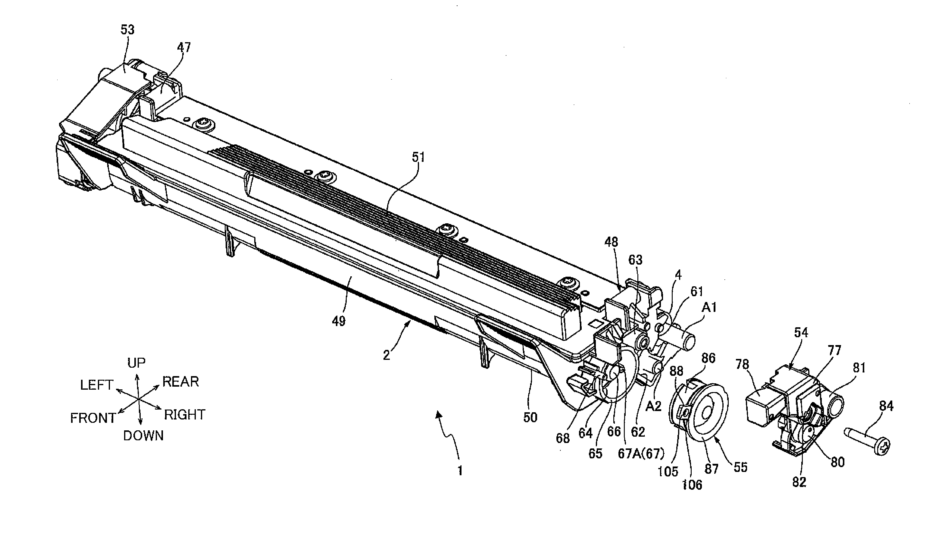
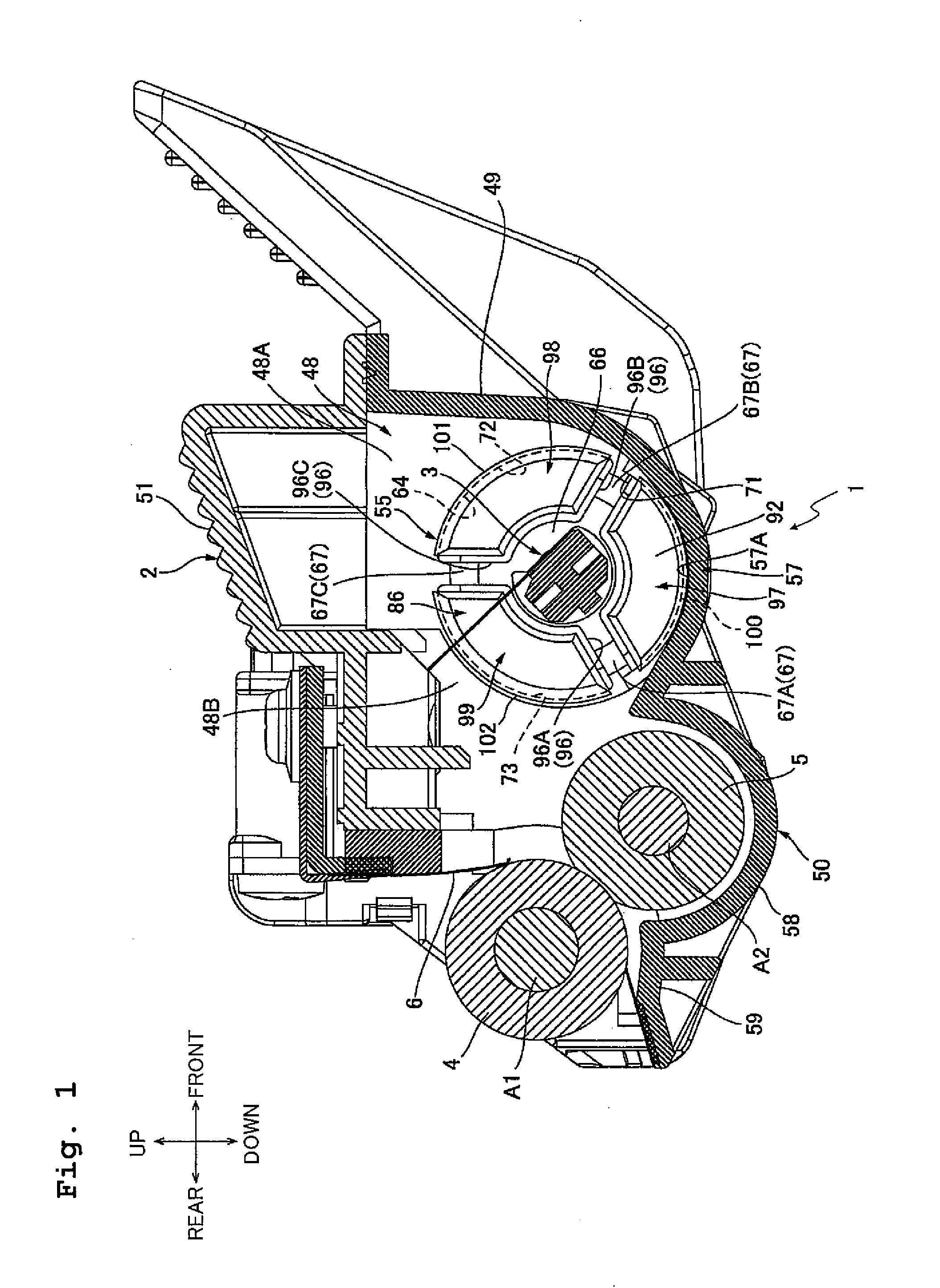
[0024]As depicted in FIG. 1, a developing cartridge 1 as an exemplary cartridge includes a developing frame 2 as an exemplary casing, an agitator 3, a supply roller 5, a developing roller 4, and a layer-thickness regulating blade 6.

[0025]In the following description, in a case that the direction concerning the developing cartridge 1 is mentioned, the direction in which the developing roller 4 is arranged is defined as the rear side of the developing cartridge 1, and the direction opposite to the direction in which the developing roller 4 is arranged is defined to as the front side of the developing cartridge 1. That is, when the sheet surface of FIG. 1 is placed in a landscape direction, the left side of FIG. 1 is defined as the rear side of the developing cartridge 1 and the right side of FIG. 1 is defined as the front side of the developing cartridge 1. Further, the upper side of FIG. 1 is defined as the upper side of the developing cartridge 1 and the lower side of FIG. 1 is defi...


PUM


Abstract

There is provided a cartridge, including: a casing including an inlet portion configured to be filled with a developer; and a lid member configured to close the inlet portion by being installed to the inlet portion from an installation direction, wherein the casing includes a first protruding portion which projects inward beyond an inner surface of the inlet portion in a direction perpendicular to the installation direction; and the lid member includes a recessed portion which is recessed from an outer surface of the lid member in the direction perpendicular to the installation direction and is configured to be engaged with the first protruding portion in a case that the lid member is installed to the inlet portion.

Description

CROSS REFERENCE TO RELATED APPLICATION[0001]The present application claims priority from Japanese Patent Application No. 2013-227751 filed on Oct. 31, 2013, the disclosure of which is incorporated herein by reference in its entirety.BACKGROUND[0002]1. Field of the Invention[0003]The present invention relates to a cartridge used in an image forming apparatus adopting an electro-photographic type, and a lid member for a cartridge.[0004]2. Description of the Related Art[0005]There is conventionally known a printer in an electro-photographic type to which a cartridge containing toner is removably installed.[0006]As the cartridge installed to the printer, there is known a toner supply container including a toner container, which contains the toner therein and has a toner filling port, and a toner cap to be installed to the toner filling port.[0007]In order to fix the toner cap to the toner filling port securely in the cartridge described in Japanese Patent Application Laid-open No. 2002-...

Claims


Application Information

Patent Timeline
IPC IPC(8): G03G15/08
CPCG03G15/0865G03G15/0872G03G15/0887G03G15/087G03G15/0881G03G15/0886G03G2215/0692
Inventor FUJII, YASUMASAMORI, HIROKI
Owner BROTHER KOGYO KK
Why Eureka
Try Eureka