
Necrotic cell region detection apparatus and method of the same, and non-transitory computer readable storage medium to store a necrotic cell region detection program

a detection apparatus and a technology for necrotic cells, applied in the field of necrotic cell region detection apparatus and method, and non-transitory computer readable storage medium to store the necrotic cell region detection program, can solve problems such as adverse effects

Active Publication Date: 2015-05-14
EVIDENT CORP
View PDF9 Cites 13 Cited by
  • Summary
  • Abstract
  • Description
  • Claims
  • Application Information

AI Technical Summary

Benefits of technology

The present invention provides a necrotic cell region detection apparatus, method, and computer program. The invention can detect regions in a cell image that are formed by necrotic cells, which are dead cells that can damage a living cell. The apparatus can acquire a group of cell images and segment the images into multiple regions with uniform imaging properties. The apparatus can then separate the images into low-band and high-band images. A feature value calculating function can calculate a texture feature value from the high-band image for each region, while a luminance calculating function can calculate a luminance average value from the low-band image for each region. A discriminant function can then form a feature space composed of the texture feature value and the luminance average value, and determine whether each region is formed by necrotic cells. The invention can provide a tool for detecting regions of dead cells in a cell image, which can help with research and development of treatments for diseases caused by necrotic cells.

Problems solved by technology

The region in which the cell contents remain due to necrosis (hereinafter referred to as a necrotic region) is difficult to distinguish from a living cell region when individual cells are extracted in cell detection, which is likely to have an adverse effect on, for example, correct measurement of the number of cells, or evaluation of the degree of cell activity by the measurement of the number of cells.

Method used


Image

  • Necrotic cell region detection apparatus and method of the same, and non-transitory computer readable storage medium to store a necrotic cell region detection program
  • Necrotic cell region detection apparatus and method of the same, and non-transitory computer readable storage medium to store a necrotic cell region detection program
  • Necrotic cell region detection apparatus and method of the same, and non-transitory computer readable storage medium to store a necrotic cell region detection program

Examples


first embodiment

[0027]Hereinafter, a first embodiment of the present invention will be described with reference to the drawings.

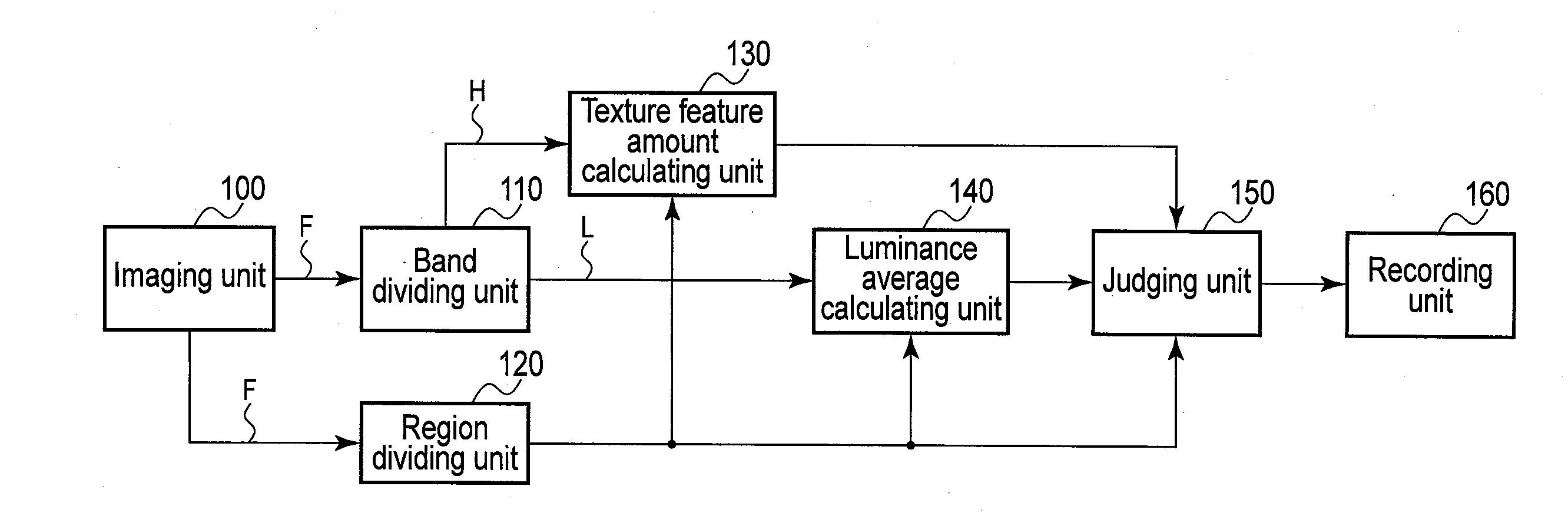
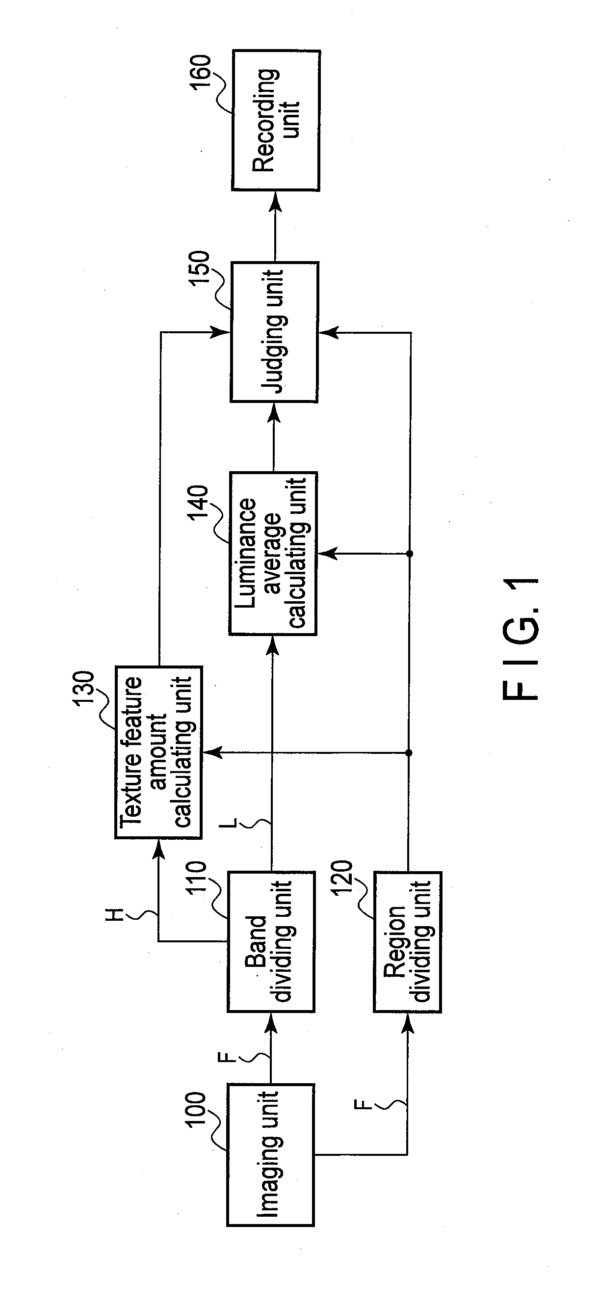
[0028]FIG. 1 shows a configuration diagram of a necrotic cell region detection apparatus. The present apparatus includes an imaging unit 100, a band separate unit 110, a segmentation unit 120, a texture feature value calculating unit 130, a luminance average calculating unit 140, a judging unit 150, and a recording unit 160.

[0029]The imaging unit 100 is connected to the band separate unit 110 and the segmentation unit 120. The band separate unit 110 is connected to the texture feature value calculating unit 130 and the luminance average calculating unit 140. The segmentation unit 120 is connected to the texture feature value calculating unit 130, the luminance average calculating unit 140, and the judging unit 150. The texture feature value calculating unit 130 and the luminance average calculating unit 140 are each connected to the judging unit 150. The judging unit 150 i...

second embodiment

[0089]Now, a second embodiment of the present invention is described with reference to the drawings. The same parts as those in FIG. 1 are indicated by the same reference signs and are not described in detail.

[0090]FIG. 9 shows a configuration diagram of a necrotic cell region detection apparatus. In the present apparatus, in contrast with the previously described first embodiment, a buffer 300 and a similarity calculating unit 310 are added, and the functions of a texture feature value calculating unit 320 and a judging unit 330 are changed.

[0091]The imaging unit 100 is connected to the band separate unit 110, the segmentation unit 120, and the similarity calculating unit 310 via the buffer 300. The band separate unit 110 and the segmentation unit 120 are connected to the luminance average calculating unit 140 and the texture feature value calculating unit 320. The segmentation unit 120 is connected to the similarity calculating unit 310. The texture feature value calculating unit ...


PUM


Abstract

A necrotic cell region detection apparatus includes an image acquiring unit, a segmentation unit, a band separate unit, a feature value calculating unit, a luminance calculating unit, and a judging unit. The image acquiring unit acquires a cell image. The segmentation unit divides the cell image into multiple regions so that a local imaging properties. The band separate unit separates a low-band image and a high-band image. The judging unit forms a feature space composed of the texture feature value calculated by the feature value calculating unit and the luminance average value calculated by the luminance calculating unit, and judges a region formed by necrotic cell in the feature space.

Description

CROSS-REFERENCE TO RELATED APPLICATIONS[0001]This application is a Continuation application of PCT Application No. PCT / JP2013 / 070105, filed Jul. 24, 2013 and based upon and claiming the benefit of priority from prior Japanese Patent Application No. 2012-169600, Jul. 31, 2012, the entire contents of all of which are incorporated herein by reference.BACKGROUND OF THE INVENTION[0002]1. Field of the Invention[0003]The present invention relates to a necrotic cell region detection apparatus and a method of the same to detect a region formed by necrotic cells from a cell image acquired by imaging using, for example, a bright field microscope, and a non-transitory computer readable storage medium to store a necrotic cell region detection program.[0004]2. Description of the Related Art[0005]Heretofore, in medical and life-science fields, various cell analyses using a cell image photographed through a microscope have been conducted. For example, in the studies of stem cells such as ES cells a...

Claims


Application Information

Patent Timeline
IPC IPC(8): G06K9/00G06K9/62
CPCG06K9/0014G06K9/6215G06K9/00147G06T7/0012G06T2207/10056G06T2207/30024G06T7/42G06V20/695G06V20/698G06F18/22
Inventor ARAGAKI, HIDEYA
Owner EVIDENT CORP
Learn More