

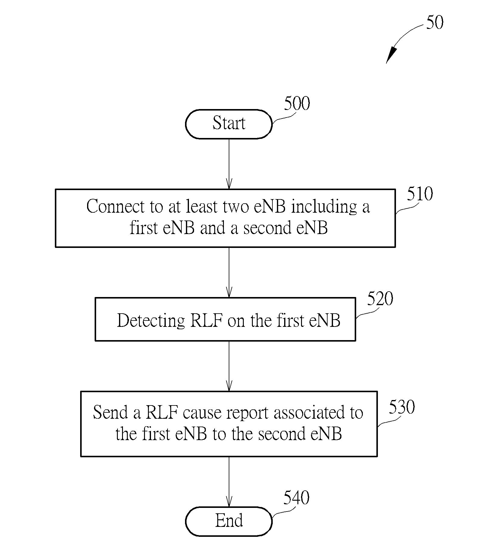
Method of Handling Radio Link Failure
a radio link and failure technology, applied in the field of communication devices, can solve problems such as the possibility of radio link failure between a ue and an enb, and the problem of rlf affecting the operation of the radio link
- Summary
- Abstract
- Description
- Claims
- Application Information
AI Technical Summary
Benefits of technology
Problems solved by technology
Method used
Image

Examples
first embodiment
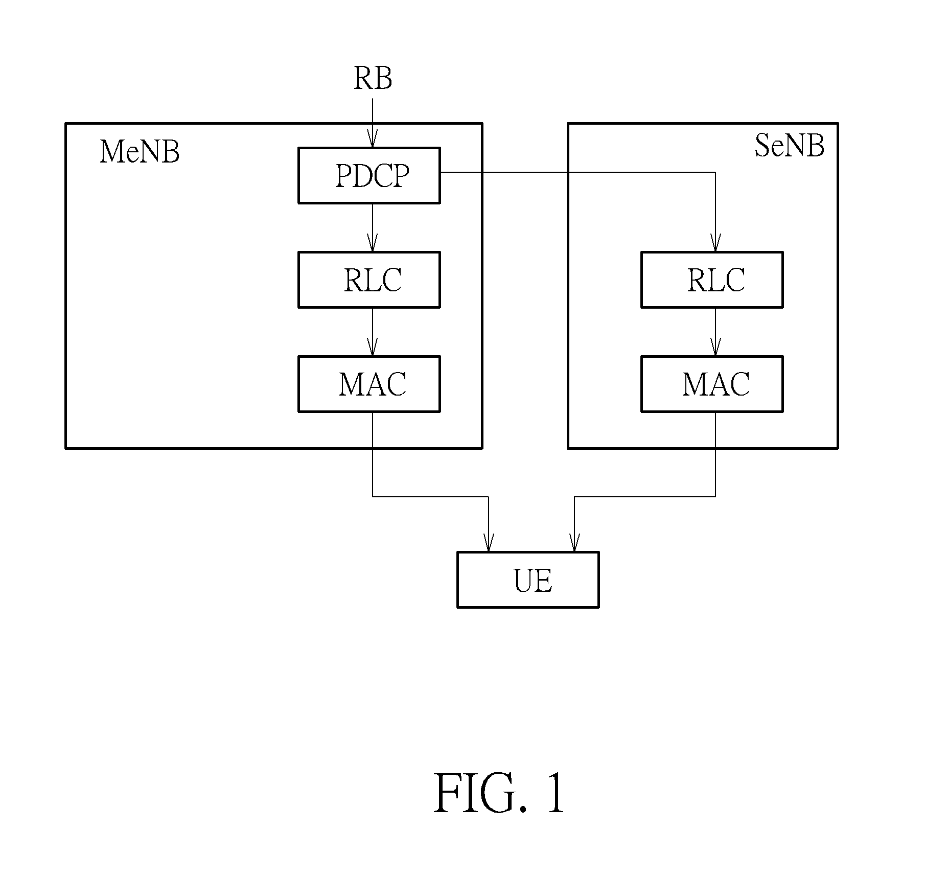
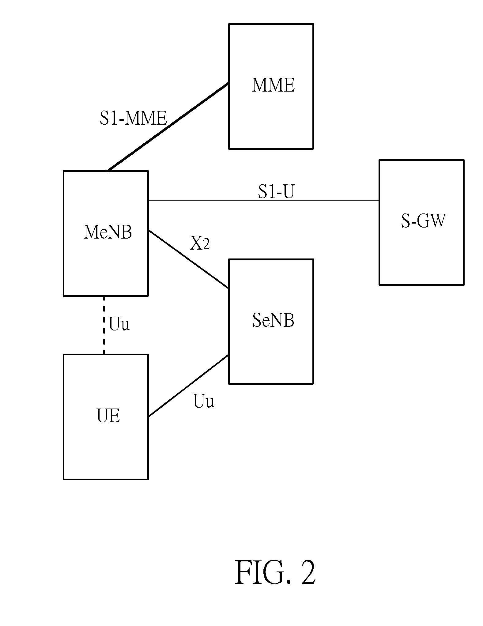
[0048]In a first embodiment, the MeNB supports split radio bearer. The architecture can be referred back to FIGS. 1-2. In the following embodiment, the second control plane option for the MeNB and SeNB is adopted. In detail, please refer to FIG. 8, which illustrates an embodiment of RLF operation in dual connectivity. In FIG. 8, the UE camps on the MeNB. Later, the MeNB adds SeNB for the UE to make the UE in dual connectivity. In dual connectivity, the MeNB and SeNB need to coordinate and exchange information for serving the UE. Once the UE detects RLF on the MeNB, it may stop transmission to and reception from the MeNB and send RLF Cause Report including as abovementioned RLF Cause A or B (i.e. indicating physical radio link problem or RLC retransmission over maximum retransmission threshold) to the SeNB. Then, the SeNB forwards the information of the RLF Cause Report to the MeNB. The MeNB would confirm whether the RLF is caused by bad signal quality. If yes, the data / signal betwee...
second embodiment
[0059]In a second embodiment, the MeNB supports split radio bearer RB1 and MeNB specific bearer RB2 as shown in FIG. 19, and the second control plane option is adopted. In detail, please refer to FIG. 20. Once the UE detects RLF on the MeNB, it may stop transmission to the MeNB and send RLF Cause Report including RLF Cause A or B to the SeNB. Then, the SeNB forward the information of RLF cause report to the MeNB. Then, the MeNB would confirm whether the RLF is caused by bad signal quality and whether the requirements of MeNB specific bearers can be satisfied while transmitting data via the SeNB. If the requirements of MeNB specific bearers can be satisfied while transmitting data via the SeNB, the MeNB sends the bearer handover request Bearer HO Request to the SeNB. If the SeNB returns bearer handover ACK Bearer HO ACK, the data and the signal between the MeNB and UE would be transmitted via the SeNB. Also, the SeNB would send the Measurement Command for the UE to measure the MeNB. ...
third embodiment
[0069]In a third embodiment shown in FIG. 30, the eNBs support only MeNB specific bearer and SeNB specific bearer, and does not support split radio bearer. In addition, the second control plane option is adopted. In detail, please refer to FIG. 31. Once the UE detects RLF on the MeNB, it may stop transmission to the MeNB and send RLF Cause Report including RLF Cause A or B to the SeNB. Then, the SeNB forward the information of RLF Cause Report to the MeNB. Then, the MeNB would confirm whether the RLF is caused by bad signal quality. If yes, the MeNB sends the bearer handover request Bearer HO Request to the SeNB. If the SeNB returns bearer handover ACK Bearer HO ACK, a path switch procedure (including bearer path switch request from the MeNB to the MME to inform the S-GW to change the bearer path from the MeNB to the SeNB, bearer path switch ACK from the MME to the MeNB, and the MeNB forwards bearer path switch ACK to the SeNB to inform the bearer path switch is complete) is perform...
PUM
 Abstract
Description
Claims
Application Information