Airbag device

a technology of airbags and valves, which is applied in the direction of pedestrian/occupant safety arrangements, vehicular safety arrangments, vehicle components, etc., can solve the problems of difficult maintenance of easy blockage of check valve channels, and difficulty in maintaining internal pressure of high-pressure-side chambers. prevent the reverse flow of gas reliably, and prevent the effect of more stably

Active Publication Date: 2015-05-21
AUTOLIV DEV AB
View PDF2 Cites 1 Cited by
  • Summary
  • Abstract
  • Description
  • Claims
  • Application Information

AI Technical Summary

Benefits of technology

[0018]Thus, the cylindrical member has a predetermined length equal to or more than a value of a sum of the first distance and the second distance. When the gas starts to flow reversely, the cylindrical member is deformed utilizing the space formed between the first end portion of the deflector and the first end portion of the inflator, and can reliably cover the first end portion of the inflator in addition to the first gap and the second gap. Consequently, the cylindrical member allows the reverse flow of the gas to be reliably prevented.
[0019]In a part of the cylindrical member which has the predetermined length, a contact portion that comes into contact with the inflator may be melted by heat generated in conjunction with ejection of the gas from the inflator, and then fixed to the inflator. Thus, the contact portion is fixed to the inflator to allow the cylindrical member to reliably prevent the reverse flow of the gas.
[0020]The cylindrical member and the division portion may be sewn so as to at least partly overlap, and a sewing line resulting from the sewing may be a curve. This avoids forming a gap between the division member and the cylindrical member and enables the first chamber and the second chamber to communicate with each other only inside the cylindrical member. Thus, the pressure of the first chamber can be maintained by allowing the cylindrical member to function as a check valve.
[0021]The cylindrical member may be formed of a coat cloth coated with silicon. The coat cloth coated with silicon has small voids. Thus, the cylindrical member formed of the coat cloth allows the reverse flow of the gas to be more stably prevented.
[0022]An aspect of the present invention can provide an airbag apparatus that prevents the reverse flow of the gas between the chambers to allow the internal pressures of the chambers to be maintained.

Problems solved by technology

However, in an airbag apparatus with a plurality of chambers, for example, when the occupant touches the cushion portion, a reverse flow of the gas may occur between the chambers, making maintenance of the internal pressures of the chambers difficult.
In such a case, the gas flows reversely from the high-pressure-side chamber to the low-pressure-side chamber, making the maintenance of the internal pressure of the high-pressure-side chamber difficult.
Thus, the tongue-like portion is easily rolled into the cylindrical portion, and the channel of the check valve is easily blocked.
However, it is difficult to control the direction in which the parts of the cloth forming the cylindrical shape stick to each other.
Thus, the technique is disadvantageous in reproducibility.
However, a change in internal pressure after the stuffing may cause the check valve to be collapsed.

Method used


Image

  • Airbag device
  • Airbag device
  • Airbag device

Examples


Embodiment Construction

[0031]Preferred embodiments of the present invention will be described below in detail with reference to the attached drawings. Dimensions, materials, other specific numeral values, and the like illustrated in the embodiments are only illustrative for facilitation of understanding of the present invention and are not intended to limit the present invention unless otherwise specified. In the specification and the drawings, elements having substantially the same functions and configurations are denoted by the same reference numerals so as to omit duplicate descriptions. Furthermore, illustration of elements that are not directly related to the present invention is omitted.

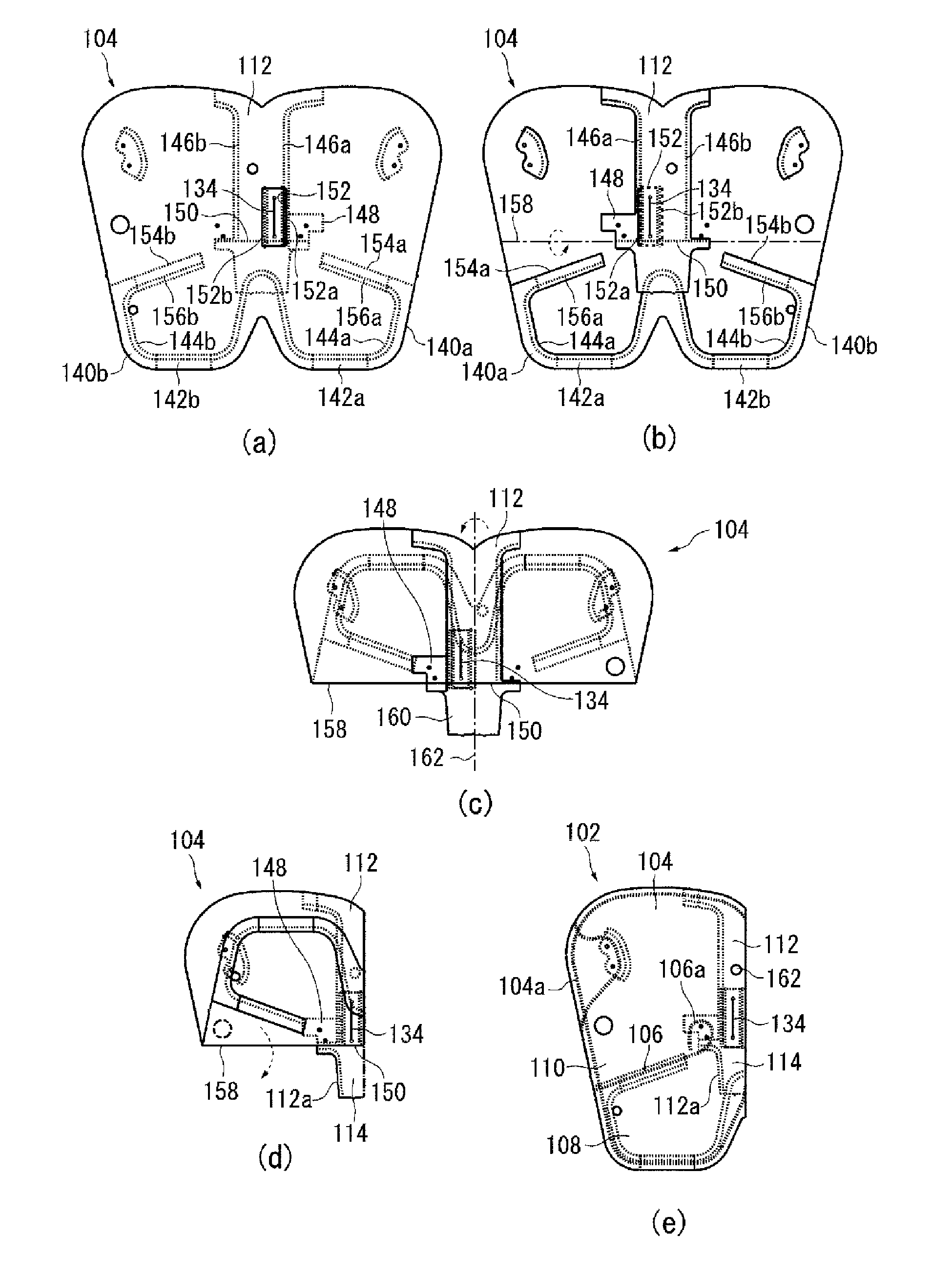
[0032]FIG. 1 is a diagram schematically illustrating an airbag apparatus according to an embodiment of the present invention. An airbag apparatus 100 includes a cushion portion 102 provided at a side portion of a vehicle seat in a vehicle to inflate and deploy between an occupant sitting in a vehicle seat and a vehic...


PUM


Abstract

An airbag apparatus that prevents a reverse flow of a gas between chambers to allow internal pressures of the chambers to be maintained. The airbag apparatus includes: a cushion portion with a divided internal space including a first chamber and a second chamber; a deflector surrounds a periphery of an inflator with a first gap therebetween to cover a gas ejection port of the inflator. The deflector has a first end portion projecting in a longitudinal direction and forming a space between the first end portions of the deflector and the inflator. A cloth cylindrical member surrounds a periphery of the deflector with a second gap therebetween. The cylindrical member projects from the first end portion of the deflector by a predetermined length so as to allow the first gap and the second gap to be covered in the first end portion side of the deflector.

Description

BACKGROUND[0001]1. Field of the Invention[0002]The present invention relates to an airbag apparatus installed in a vehicle to inflate and deploy mainly in order to protect an occupant in case of emergency.[0003]2. Description of Related Art[0004]An airbag apparatus is a safety apparatus that operates in case of emergency, such as a vehicle collision, and includes, for example, a bag-like cushion portion. The cushion portion is inflated and deployed by a gas, during an emergency, to receive and protect an occupant. Various types of airbag apparatuses are available depending on the installation position or application. By way of example, a side airbag is known which inflates and deploys from a side portion of a vehicle seat to a position immediately beside the occupant in order to protect the occupant in a side impact and a possible subsequent rollover (overturn).[0005]The airbag apparatus includes a gas generating apparatus called an inflator and which supplies a gas to the cushion p...

Claims


Application Information

Patent Timeline
Patent Type & Authority Applications(United States)
IPC IPC(8): B60R21/26B60R21/231
CPCB60R21/231B60R21/26B60R21/233B60R21/2346B60R21/261B60R2021/2612
Inventor KATO, YOSHIYUKIMIYAGI, KOICHI
Owner AUTOLIV DEV AB
Why Eureka
Try Eureka