Rotor securing arrangement and rotating electric machine having the same
- Summary
- Abstract
- Description
- Claims
- Application Information
AI Technical Summary
Benefits of technology
Problems solved by technology
Method used
Image
Examples
first modification
[0060](First Modification)
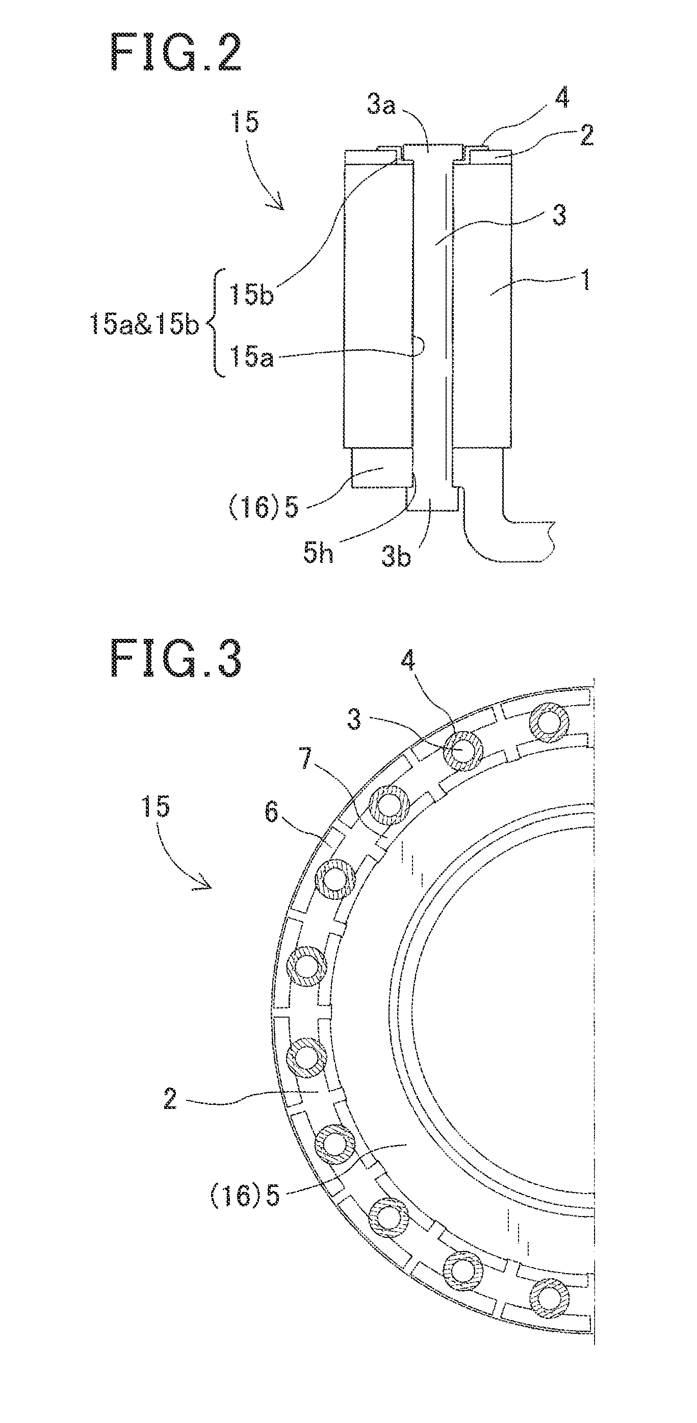
[0061]In a first modification of the embodiment set forth above, a second securing member 44 as shown in FIGS. 7-9 is used in place of the second securing member 4 as shown in FIGS. 2-5. The second securing member 44 is similar to the second securing member 4 except that they are different in shape. The second securing member 44 is an elongated plate-like member extending over two or more poles of the rotor 15. The second securing member 44 as shown in FIG. 7 is an annular flat-plate member extending over a plurality of poles.
[0062]Referring to FIG. 8, the second securing member 44 includes a body 44a, a plurality of recesses 44b, a plurality of through holes 44c and others. The body 44a is an elongated plate-like portion. Each recess 44b is formed in a portion of the body 44a corresponding to one of the first securing members 3 (through hole 15a&15b) and is configured to fit within the through hole of the second diameter R2 in the second rotor core 2. The ...
second modification
[0077](Second Modification)
[0078]In a second modification of the embodiment set forth above, a securing member 30 as shown in FIG. 10 is used in place of the first securing member 3 and the second securing member 4 as shown in FIGS. 2-5. The securing member 30 is a single member that integrates the first securing member 3 and the second securing member 4. Use of the securing member 30 can reduce the number of components, thereby reducing the number of operations for securing the rotor 15 to the disc 5.
third modification
[0079](Third Modification)
[0080]In a third modification of the embodiment set forth above, a second securing member 45 as shown in FIG. 11 is used in place of the second securing member 4 as shown in FIGS. 2-5. The second securing member 45 includes a tapered portion 45a corresponding to the seat portion 4a and a stepped portion 45b corresponding to the stepped portion 4b. The tapered portion 45a is inclined at an angle 8 relative to the end face of the rotor 15 (more specifically, the end face of the second rotor core 2). A core-side surface of the tapered portion 45a (a lower side surface of the tapered portion 45a in FIG. 11) and a anti-core-side surface of the tapered portion 45a (an upper side surface of the tapered portion 45a in FIG. 11) may be parallel with each other. A portion of the tapered portion 45a (right and left ends in FIG. 11) presses upon the second rotor core 2. As with the stepped portion 4b, the stepped portion 45b presses upon the first rotor core 1.
[0081]The...
PUM
 Abstract
Description
Claims
Application Information
 - R&D
- Intellectual Property
- Life Sciences
- Materials
- Tech Scout
- Unparalleled Data Quality
- Higher Quality Content
- 60% Fewer Hallucinations
Browse by: Latest US Patents, China's latest patents, Technical Efficacy Thesaurus, Application Domain, Technology Topic, Popular Technical Reports.
© 2025 PatSnap. All rights reserved.Legal|Privacy policy|Modern Slavery Act Transparency Statement|Sitemap|About US| Contact US: help@patsnap.com


