Differential device

Inactive Publication Date: 2017-06-01
MUSA PRECISION IND
View PDF0 Cites 4 Cited by
  • Summary
  • Abstract
  • Description
  • Claims
  • Application Information

AI Technical Summary

Benefits of technology

The present invention relates to a differential device that allows differential rotation of left and right or front and rear driven wheels of an automobile. The device includes an input plate and a cover that form a differential case, with a first output shaft and a second output shaft. The device uses a cycloid reduction mechanism or a trochoid reduction mechanism to minimize its axial length and make it compact. The differential case is supported on the transmission case of the automobile, and the eccentric shaft and differential plates are held within the differential case. The device allows for equal distribution of torque between the output shafts and reduces the torque transmitted through the rolling bodies, improving their strength and durability. The device is also suitable for use in a two-stage type transmission mechanism.

Problems solved by technology

A differential device employing a ball mechanism as in Patent Document 1 is known, but since in this device, it is essential to provide a center plate for generating a reaction force by holding a ball between a pair of guide plates, which form a differential mechanism, when there is differential motion the ball undergoes a sliding motion against a guide hole of the center plate and experiences resistance, thereby resulting in degradation of the fuel consumption performance
Furthermore, a cycloid type transmission mechanism as in Document 2 in the related art is also known, but this is a simple transmission mechanism, and its application as a differential device is difficult.

Method used


Image

  • Differential device
  • Differential device
  • Differential device

Examples


first embodiment

[0086]First, referring to FIG. 1 to FIG. 7, a first embodiment in which the differential device of the present invention is used as an automobile differential device is explained.

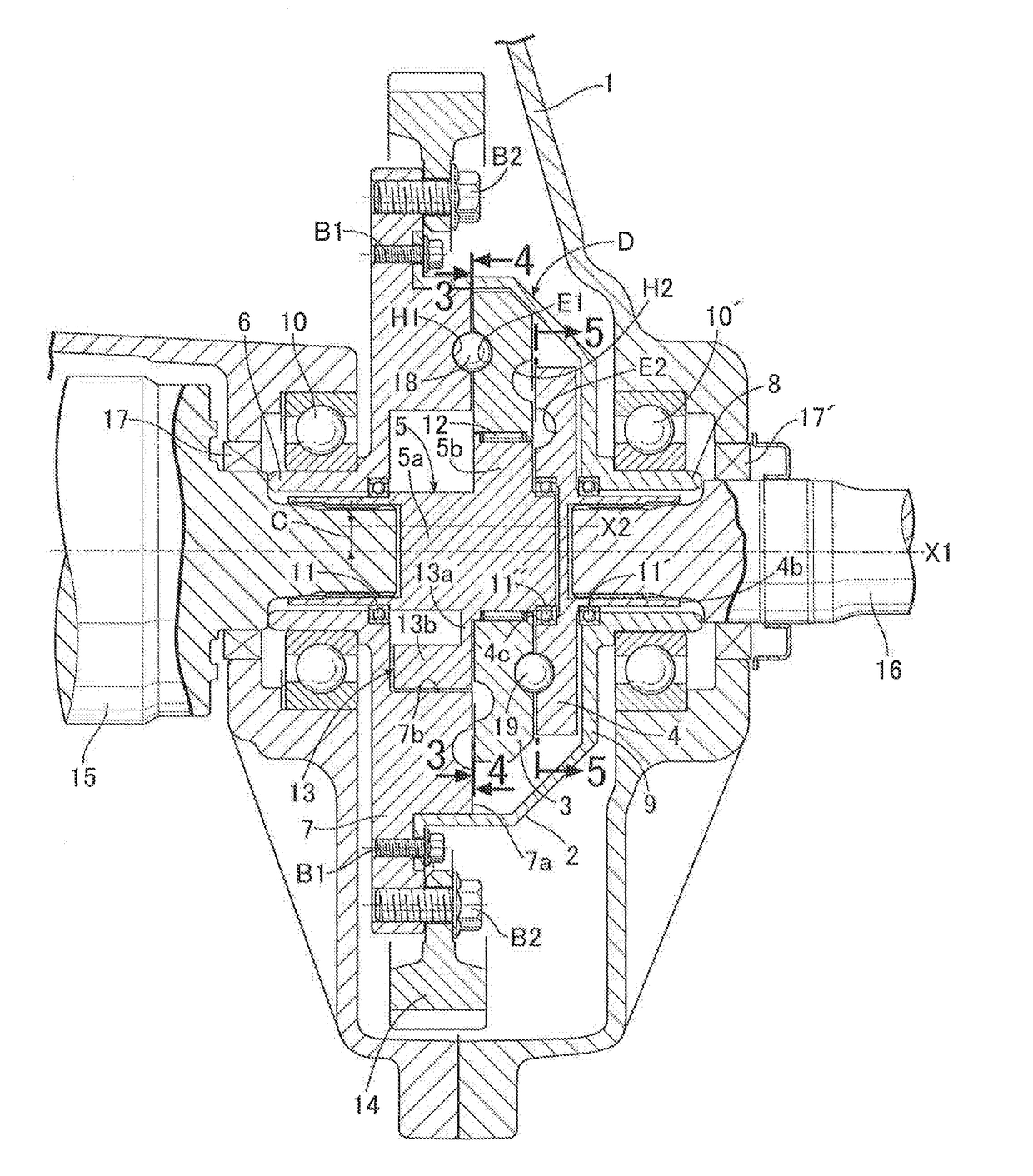
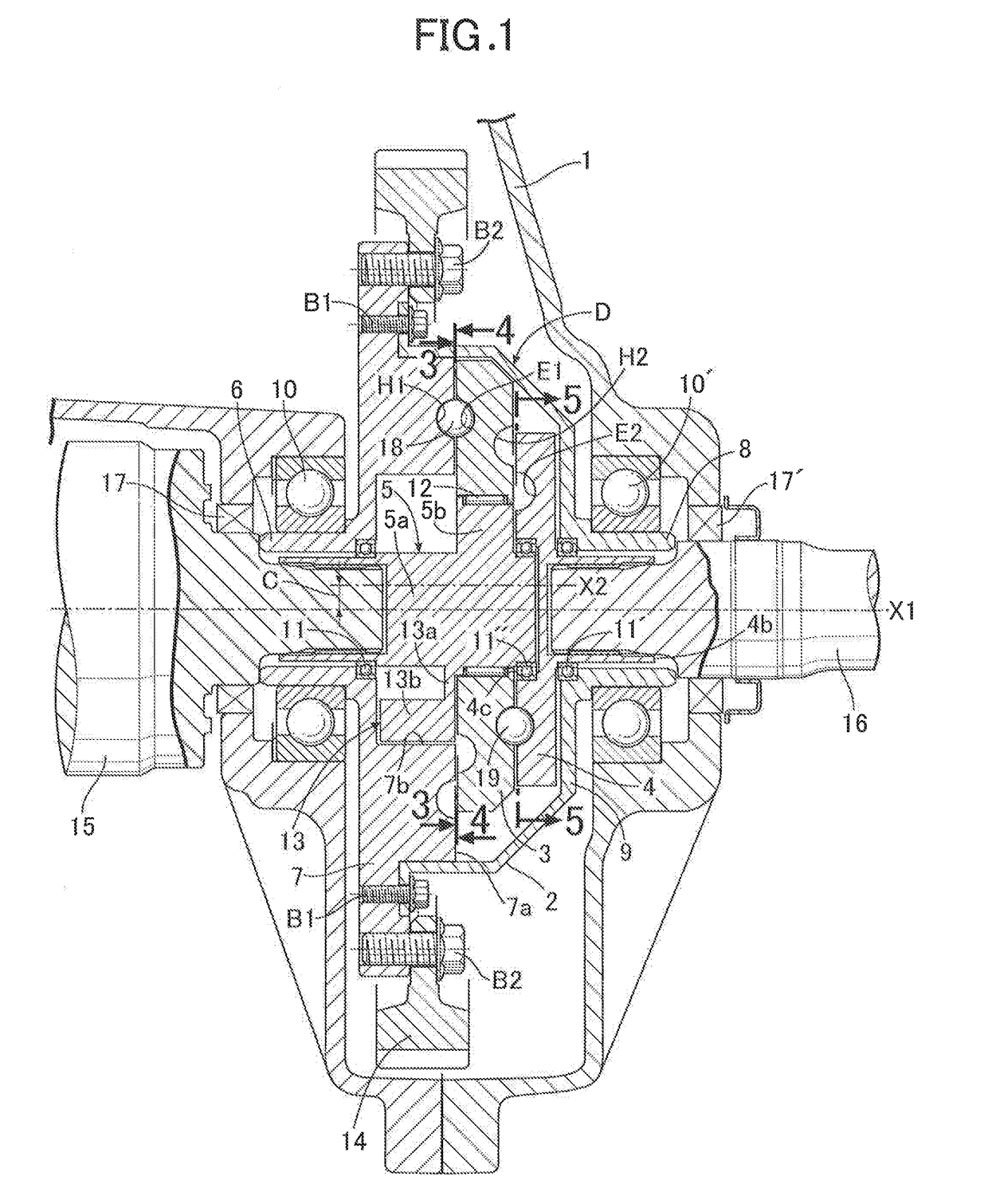
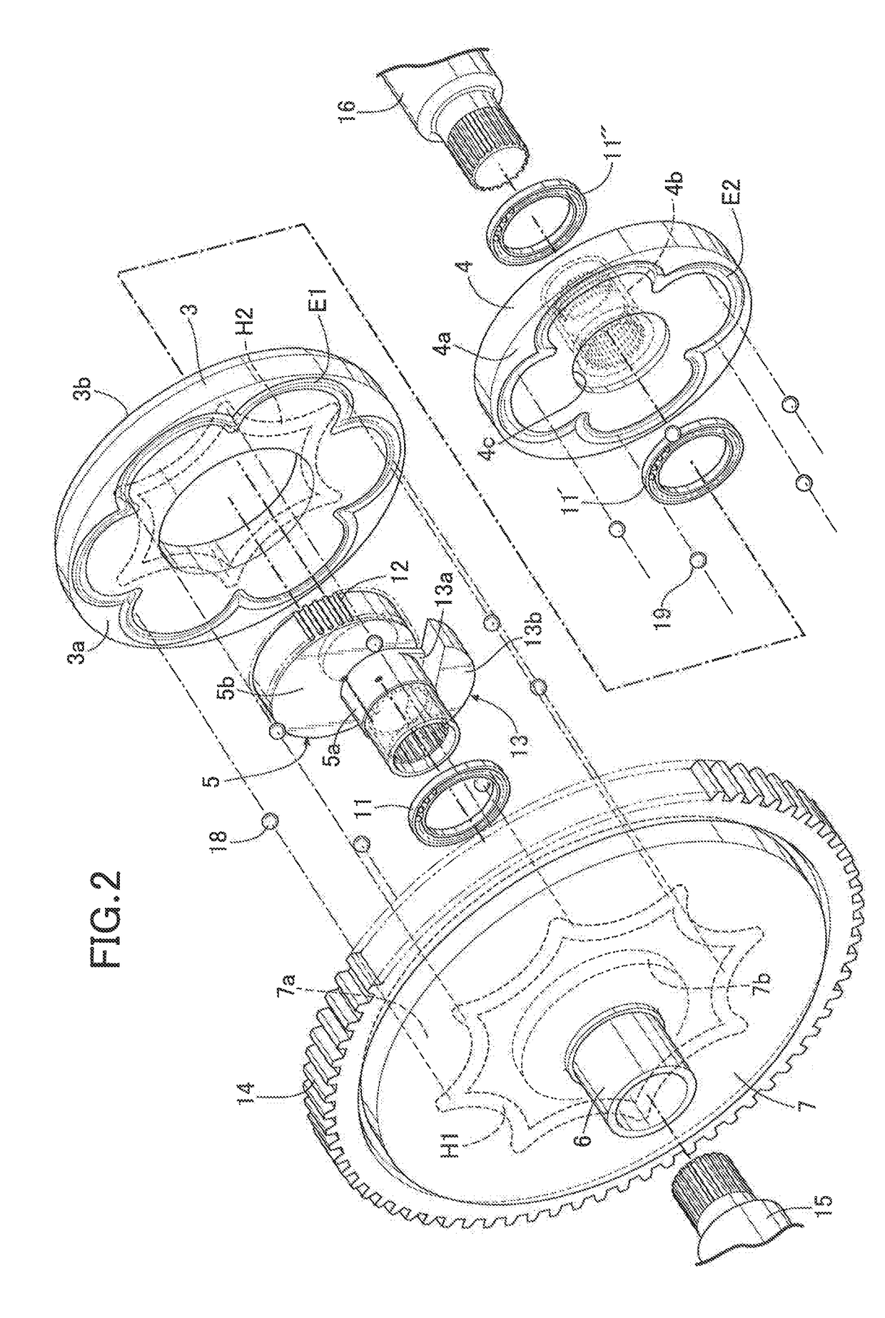
[0087]In FIG. 1, a differential device D housed within an automobile transmission case 1 includes a differential case 2, and first and second differential plates 3 and 4 and an eccentric shaft 5 housed within the differential case 2. The differential case 2 is formed from a circular input plate 7 that has a hollow cylindrical first shaft 6 and a cover 9 that has a hollow cylindrical second shaft 8 arranged on the same axis as the first shaft 6 and whose outer periphery is fixed to an outer peripheral part of the input plate 7 via a bolt B1 while covering the first and second differential plates 3 and 4 and the eccentric shaft 5, these first and second shafts 6 and 8 being supported on the transmission case 1 via bearings 10 and 10′ so as to be rotatable around a first rotational axis X1.

[0088]The first diff...

second embodiment

[0134]A second embodiment in which the differential device of the present invention is used as an automobile differential device is now explained by reference to FIG. 8.

[0135]The second embodiment described in FIG. 8 is one in which an auxiliary balancer 20 is added to the differential device of the first embodiment, and is different from the differential device of the first embodiment only in respect of a cylindrical auxiliary cutout portion 4d opposing the cutout portion 7b of the input plate 7 with the first differential plate 3 sandwiched therebetween being formed in a middle part of the one side face 4a of the second differential plate 4, and the auxiliary balancer 20 linked to the eccentric shaft 5 being disposed within the auxiliary cutout portion 4d so as to revolve around the first rotational axis X1 with a phase that is displaced by 180 degrees from the phase of the center of gravity of the first differential plate 3 rotating around the first rotational axis X1, the remain...

third embodiment

[0143]A third embodiment of the present invention is now explained by reference to FIG. 9.

[0144]In the third embodiment, the first differential plate 3 in FIG. 1 is formed from a pair of rotating plates 3c and 3d linked via a linking member 3e so that they can rotate as a unit.

[0145]That is, in the third embodiment, one side face of the first rotating plate 3c opposes the one side face 7a of the input plate 7, one side face of the second rotating plate 3d opposes the one side face 4a of the second differential plate 4, and the other side face of the first rotating plate 3c and the other side face of the second rotating plate 3d are linked to each other across a gap via a plurality of the rod-shaped linking members 3e disposed on outer peripheral parts thereof at equal intervals in the peripheral direction. Furthermore, the first epi groove part E1 opposing the first hypo groove part H1 of the input plate 7 is formed in the one side face of the first rotating plate 3c, the second hyp...


PUM


Abstract

A differential device is provided in which a first wave number (Z1) of a first hypo groove part on an input plate, a second wave number (Z2) of a first epi groove part on a first differential plate and opposing the first hypo groove part, a third wave number (Z3) of a second hypo groove part on the first differential plate and on the opposite side from the first epi groove part, and a fourth wave number (Z4) of a second epi groove part on a second differential plate and opposing the second hypo groove part are set as Z1=8, Z2=Z3=6 and Z4=4, or as Z1=Z4=6, Z2=4, Z3=8. Such differential device enables equal torque distribution and equal differential rotation via a cycloid reduction mechanism without using a bevel gear or a center plate.

Description

TECHNICAL FIELD[0001]The present invention relates to a differential device with a new mechanism that distributes rotational power of an input plate between a first output shaft and a second output shaft relatively rotatably arranged on the same rotational axis via a cycloid reduction mechanism or a trochoid reduction mechanism and, in particular, to one that is suitably used as a differential device that allows differential rotation between left and right or front and rear driven wheels of an automobile.BACKGROUND ART[0002]In a conventional differential device employing a bevel gear, not only is it impossible to avoid the occurrence of a teeth-rattling noise and a thrust component force, which are characteristic of bevel gear meshing, but since the number of simultaneously-meshing teeth are only some of the total number of teeth, the torque is also borne only by some of the teeth, and there is room for improvement in terms of strength and durability.[0003]A differential device empl...

Claims


Application Information

Patent Timeline
IPC IPC(8): F16H48/14F16H57/037
CPCF16H57/037F16H48/14F16H48/05
Inventor NOGUCHI, TAKANORIHAMADA, TETSUROSAKATA, SHOHEI
Owner MUSA PRECISION IND
Why Eureka
Try Eureka