Wireless communication apparatus and method, and signal attenuation prediction apparatus and method

Inactive Publication Date: 2007-07-26
SONY CORP
View PDF6 Cites 24 Cited by
  • Summary
  • Abstract
  • Description
  • Claims
  • Application Information

AI Technical Summary

Benefits of technology

[0012]In view of the above, it is desirable to provide a wireless communication apparatus and method as well as a signal attenuation prediction apparatus and method for reducing calculation load of combining a modulation mode and transmission power and efficiently deriving the optimum combination.
[0019]According to an embodiment of the invention, by predicting the amount of signal attenuation along a wireless transmission line and calculating the modulation method and the level of the transmission signal that provides minimum communication power consumption based on the predicted amount of signal attenuation, the optimum combination of the modulation mode and the transmission power can be efficiently derived with less calculation load.

Problems solved by technology

Particularly, it is difficult to determine the optimum solution in an efficient manner because the evaluation equation contains a discontinuous function.
For example, to determine the optimum solution, possible parameter values are substituted into the evaluation equation in a brute force manner and the calculation results are compared to narrow the optimum solution, which may require enormous calculation, so that it is difficult to save power.

Method used


Image

  • Wireless communication apparatus and method, and signal attenuation prediction apparatus and method
  • Wireless communication apparatus and method, and signal attenuation prediction apparatus and method
  • Wireless communication apparatus and method, and signal attenuation prediction apparatus and method

Examples


Embodiment Construction

[0031]A specific embodiment of the invention will be described below in detail with reference to the drawings. Although the embodiment will be described with reference to a wireless LAN (Local Area Network), the embodiment is not limited thereto.

[0032]A wireless LAN can be built either using the infrastructure mode or the ad hoc mode. Although the invention can be adapted to either network, the following description will be made with reference to the infrastructure mode. The DCF (Distributed Coordination Function) mode or the PCF (Point Coordination Function) mode will be used as the access method during data transmission, and the following description will be made with reference to the PCF mode.

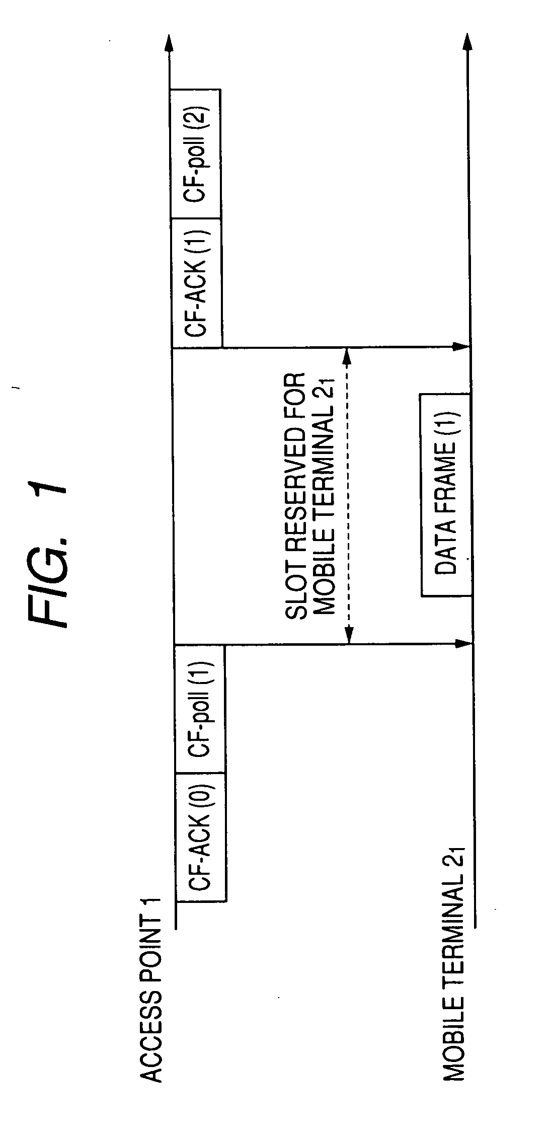
[0033]FIG. 1 explains how to transmit data from a mobile terminal 2 to an access point 1 in a wireless LAN operated in the PCF mode. As shown in FIG. 1, the access point 1 multicasts Poll frames containing the MAC address of the mobile terminal 2 to all mobile terminals 20 to 2n connected to...


PUM


Abstract

A wireless communication apparatus that transmits a transmission signal and receives a reception signal via a wireless transmission line, the wireless communication apparatus including prediction means for predicting the amount of signal attenuation along the wireless transmission line, a first conversion table that converts the level of the transmission signal into a first power consumption calculation parameter for each modulation method for the transmission signal, a second conversion table that converts C / N of the transmission signal into a second power consumption calculation parameter for each modulation method for the transmission signal, calculation means for calculating the modulation method and the level of the transmission signal that provide minimum power consumption based on the amount of signal attenuation predicted by the prediction means, the first conversion table and the second conversion table, and control means for controlling the modulation method and the level of the transmission signal based on the calculation result calculated by the calculation means.

Description

CROSS REFERENCES TO RELATED APPLICATIONS[0001]The present invention contains subject matter related to Japanese Patent Application JP 2006-016800 filed in the Japanese Patent Office on Jan. 25, 2006, the entire contents of which being incorporated herein by reference.BACKGROUND OF THE INVENTION[0002]1. Field of the Invention[0003]The present invention relates to an apparatus and method using wireless communication, such as a wireless LAN (Local Area Network), and a signal attenuation prediction apparatus and method.[0004]2. Description of the Related Art[0005]In recent years, battery-driven terminals having wireless communication capabilities have been widely used. An example of the wireless communication capability may be a wireless LAN (Local Area Network), such as IEEE 802.11a / b / g.[0006]In related art, a major challenge of a desktop wireless communication instrument that uses transmitting and receiving terminals having a fixed distance therebetween is maximization of communicatio...

Claims


Application Information

Patent Timeline
IPC IPC(8): H04L27/00H04W52/04H04W52/22H04W52/24
CPCH04L1/0003H04L1/0009H04L1/18H04L27/0008H04L1/203H04W52/226H04W52/242H04W52/246Y02B60/50H04W52/04
Inventor MIYABAYASHI, NAOKI
Owner SONY CORP
Why Eureka
Try Eureka