Power transmission system

Active Publication Date: 2015-10-15
GPOUER
View PDF2 Cites 1 Cited by
  • Summary
  • Abstract
  • Description
  • Claims
  • Application Information

AI Technical Summary

Benefits of technology

[0006]Accordingly, an object of the present invention is to provide a power transmission system, which can efficiently transmit power produced by the working fluid, that is, the

Problems solved by technology

However, for the power transmission from the transmission shaft to the specific components or equipments, there are still some flaws in the specific components or equipments during the operation for energy formation, which often prevents efficiency of power transmission from being promoted, for example, the traditional equipments could not emit the accumulated exhaust gas thoroughly generated from the incomplete emission of exhaust gas; as a result, power transmission is less efficient than expected, which may shorte

Method used


Image

  • Power transmission system
  • Power transmission system
  • Power transmission system

Examples


Example

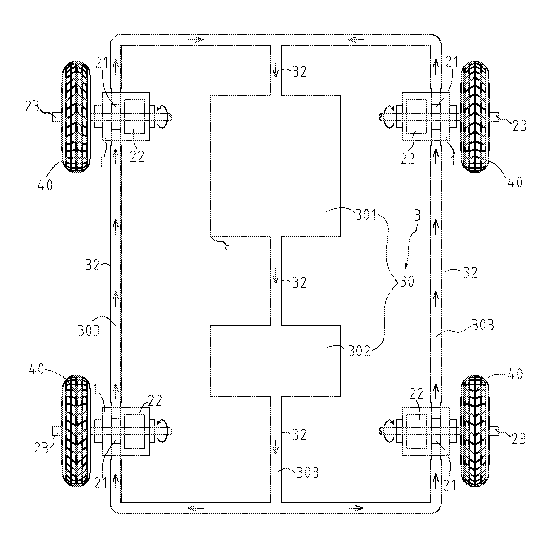
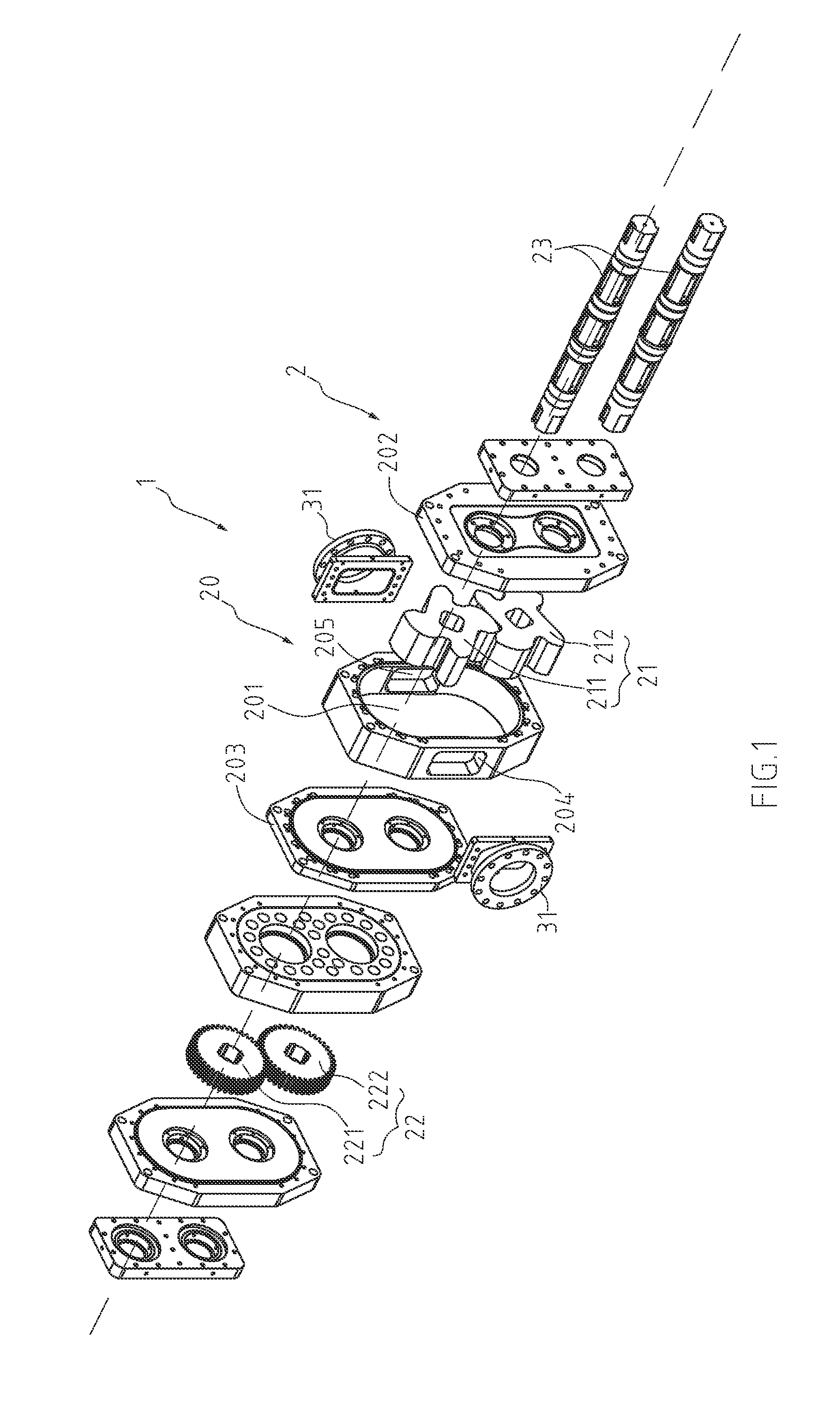
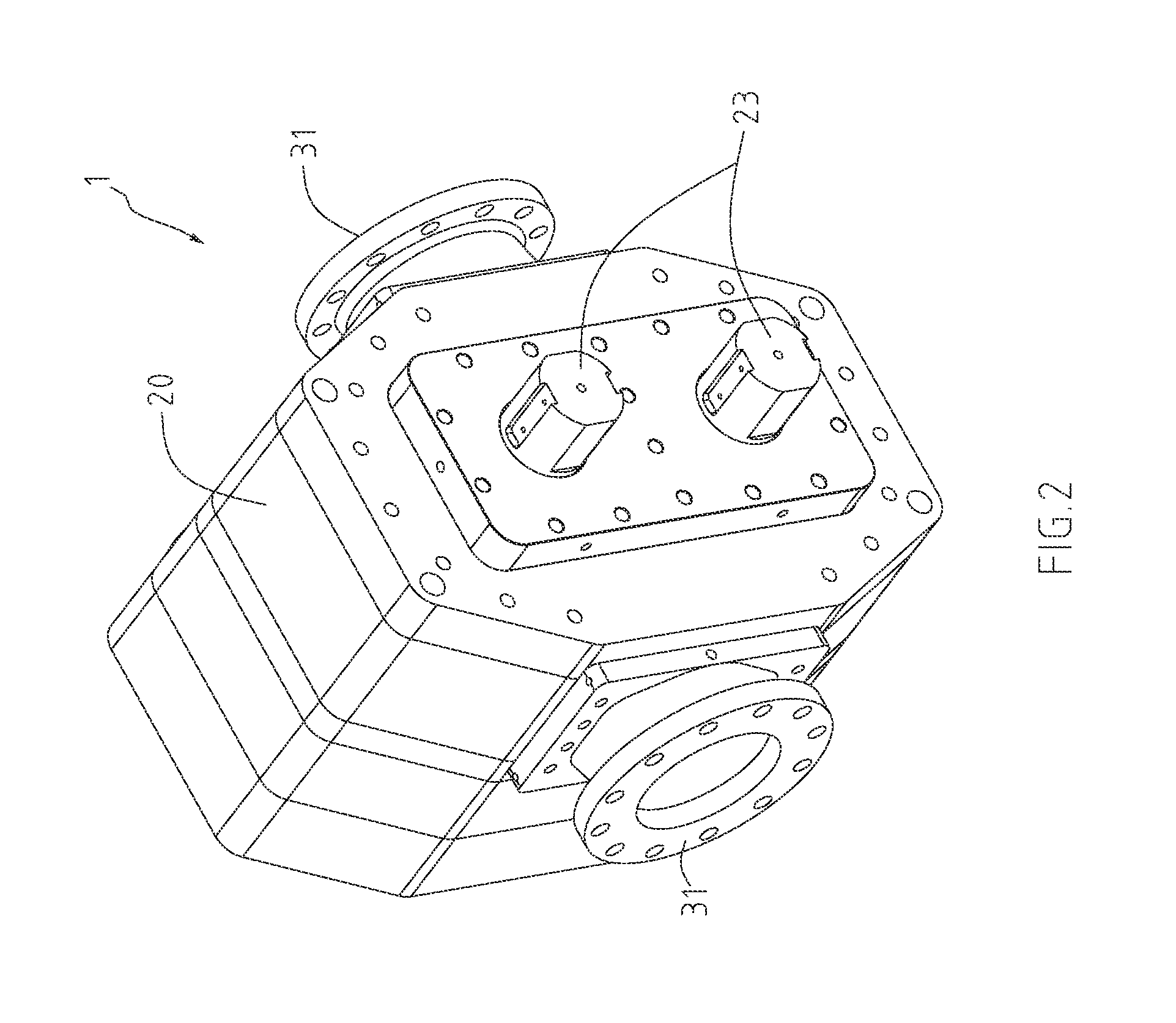
[0021]Please referring to FIG. 1 and FIG. 2, as shown, power transmission system 1 in accordance with the present invention comprises a transmission device 2, and a power supply device 3 which powers the transmission device 2, wherein the transmission device 2 further comprises a cavity 20, a pair of rotors 21, a gear set 22, and a transmission shaft 23. The cavity 20 has a body 201, covers 202, 203, an inlet 204 and an outlet 205, wherein the inlet 204 and the outlet 205 are defined on the body 201; the inlet 204 provides the inflow of working fluid into the cavity 20, while the outlet 205 provides the outflow of working fluid from the cavity 20. The gear set 22 comprises a first gear 221 and a second gear 222 intermeshed with each other, both of which have same number of teeth and belong to a spur gear (or a helical gear).

[0022]The power supply device 3 (referring to FIG. 3) comprises a power equipment 30 available for transmitting a working fluid, and shaft adapters 31 connected ...


PUM


Abstract

A power transmission system comprises a transmission device, and a power supply device which powers the transmission device, wherein the transmission device comprises a cavity having a body, covers, an inlet and an outlet; at least a pair of rotors and a gear set that are assembled in the cavity; and a transmission shaft pivotally connected with the pair of rotors and the gear set; the power supply device comprises a power equipment available for transmitting a working fluid; shaft adapters connected with the inlet and the outlet of the cavity; and a connecting pipe connected between the power equipment and the shaft adapter; the working fluid is transmitted by the connecting pipe from the power equipment to the inlet of the cavity to provide the pair of rotors with normal force for radial motion in a reverse rotation direction and make pressure in the cavity increased.

Description

BACKGROUND OF THE INVENTION[0001]1. Field of the Invention[0002]The present invention relates to a power transmission system, and more particularly to a system that as able to transmit power produced by working fluid in an efficient way and provide high-lift transmission effect in accordance with the transmitted power.[0003]2. The Related Art[0004]Power comes from energy conversion involving different conversion amount and speed rate. The common power transmission is provided by transmission shaft to transmit power to specific components or equipments, so that amount of work can directly affect performance of the specific components or equipments. Common power driver includes engine, vacuum pump, internal combustion engine, compressor, etc., by which working fluid produces power during its transmission and then the power is transmitted from the transmission shaft to the specific components or equipments, e.g., fans or gear set, that is, the work done by the transmission shaft provid...

Claims


Application Information

Patent Timeline
IPC IPC(8): F16H47/02
CPCF16H47/02B60K7/0015B60K7/0023B60K17/043F01C1/123F16H57/02F16H61/40
Inventor HSU, TSANG-LINYEH, JUNG-FENGLU, JAU-HUAICHUNG, TIEN-TUNGLIN, JIAN-HUNGLIU, CHIA-CHUN
Owner GPOUER
Why Eureka
Try Eureka