
Acoustic equipment

a technology for audio equipment and audio devices, applied in the direction of transducer details, stereophonic circuit arrangements, cabinets, etc., can solve the problems that users cannot perform the audio-device mounting operation in a smooth and reliable manner, and achieve the effect of improving the fixation for

Active Publication Date: 2015-05-28
YAMAHA CORP
View PDF9 Cites 0 Cited by
  • Summary
  • Abstract
  • Description
  • Claims
  • Application Information

AI Technical Summary

Benefits of technology

The present invention provides an improved audio device that can be easily mounted on a stand with a pole. The audio device has a pressing member that can be pivoted in the tightening direction to securely hold the pole in place. The pressing member has a stopping / engaging section that gradually increases the pressure on the pole as it is pressed, allowing for smooth and reliable mounting. The user can easily dismount the audio device by reversing the pressing member. The audio device also includes a provisional engaging section to further stabilize the attachment to the pole. The audio device can be inserted and removed from the pole with minimal friction, and the pole can be securely grasped and fixed between the pressing member and the stopping / engaging section. The pressing member has a curved surface portion that closely matches the outer peripheral side of the pole for enhanced fixation force. The pressing member also has a retaining section to prevent it from swaying in the loosened position. Overall, the present invention simplifies the mounting process and provides a more stable and reliable attachment for the audio device to the stand.

Problems solved by technology

As a result, the user can not only perform the audio-device mounting operation in a smooth and reliably manner.

Method used


Image

  • Acoustic equipment
  • Acoustic equipment
  • Acoustic equipment

Examples


Embodiment Construction

[0018]Hereinbelow, a description will be given about embodiments of the present invention with reference to the accompanying drawings.

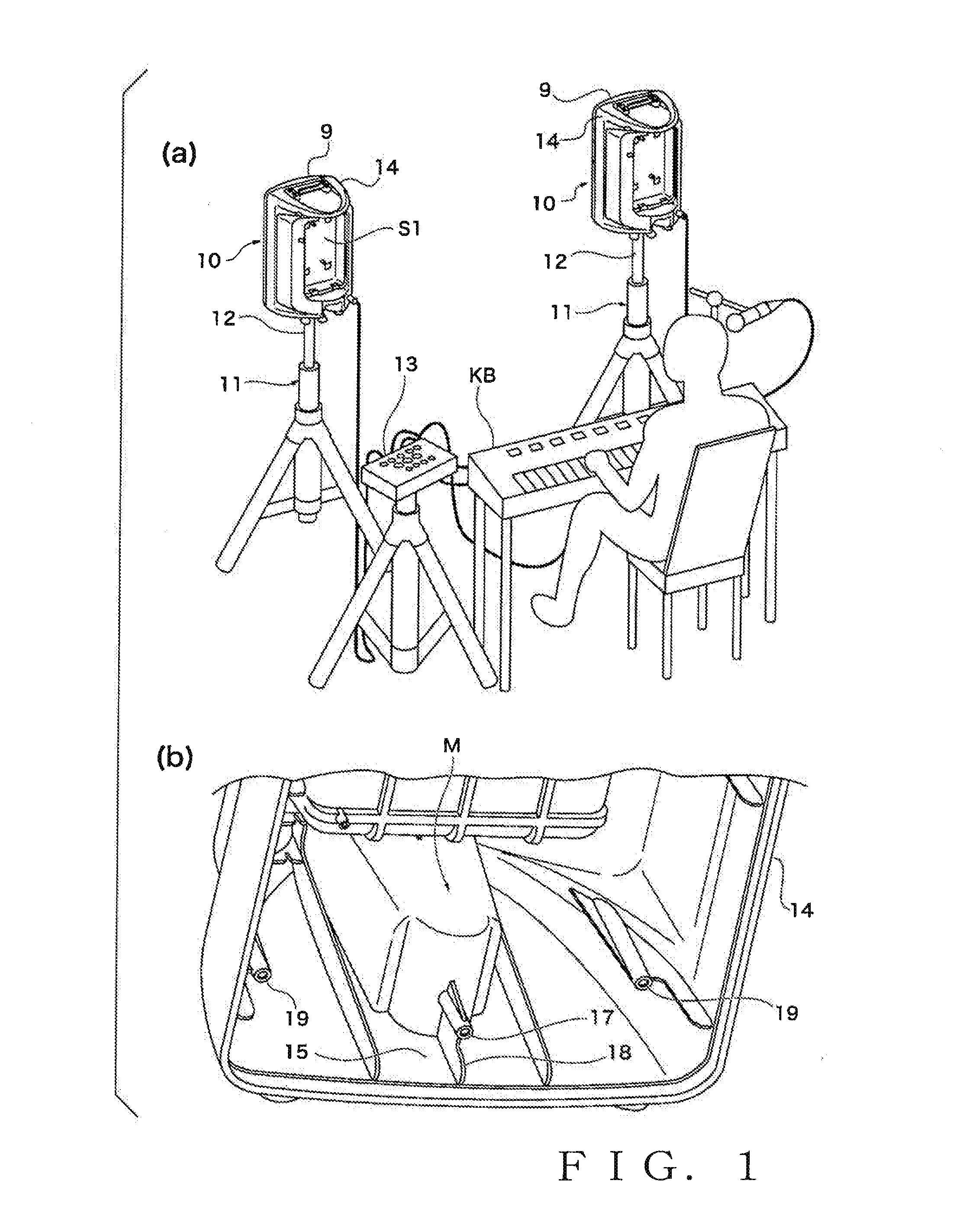
[0019]FIG. 1(a) is a view showing an example of a usage state of a speaker set to which acoustic equipment or audio device according to an embodiment of the present invention is applied (a state where the audio device has been mounted on a stand). In the instant embodiment, the audio device is fixedly mounted on the stand 11 by be attached to a pole 12 of a circular columnar pole of the stand 11. Whereas a pair of left and right speaker devices 10 are illustratively shown as the acoustic equipment or audio devices. The basic principles of the present invention are applicable to various other audio devices than speakers, such as a mixer apparatus.

[0020]An electronic keyboard musical instrument KB is connected to a mixer apparatus 13, and the speaker devices 10 are connected to the mixer apparatus 13. When not in use, the mixer apparatus 13 can be accom...


PUM


Abstract

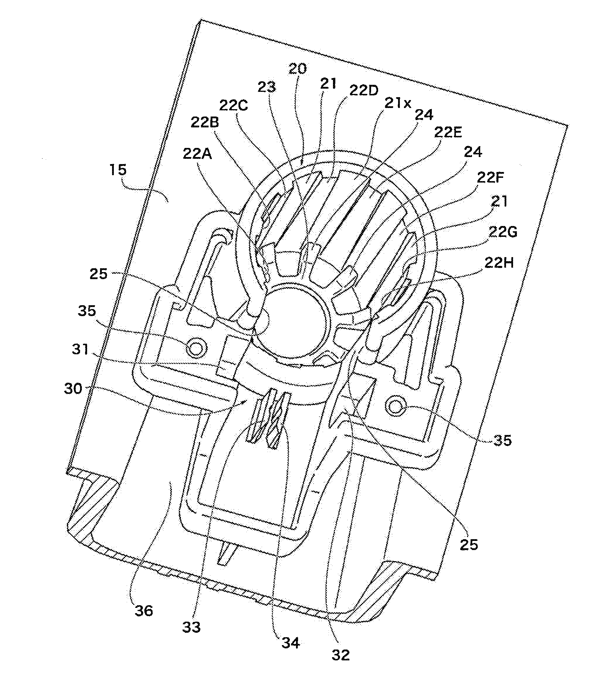
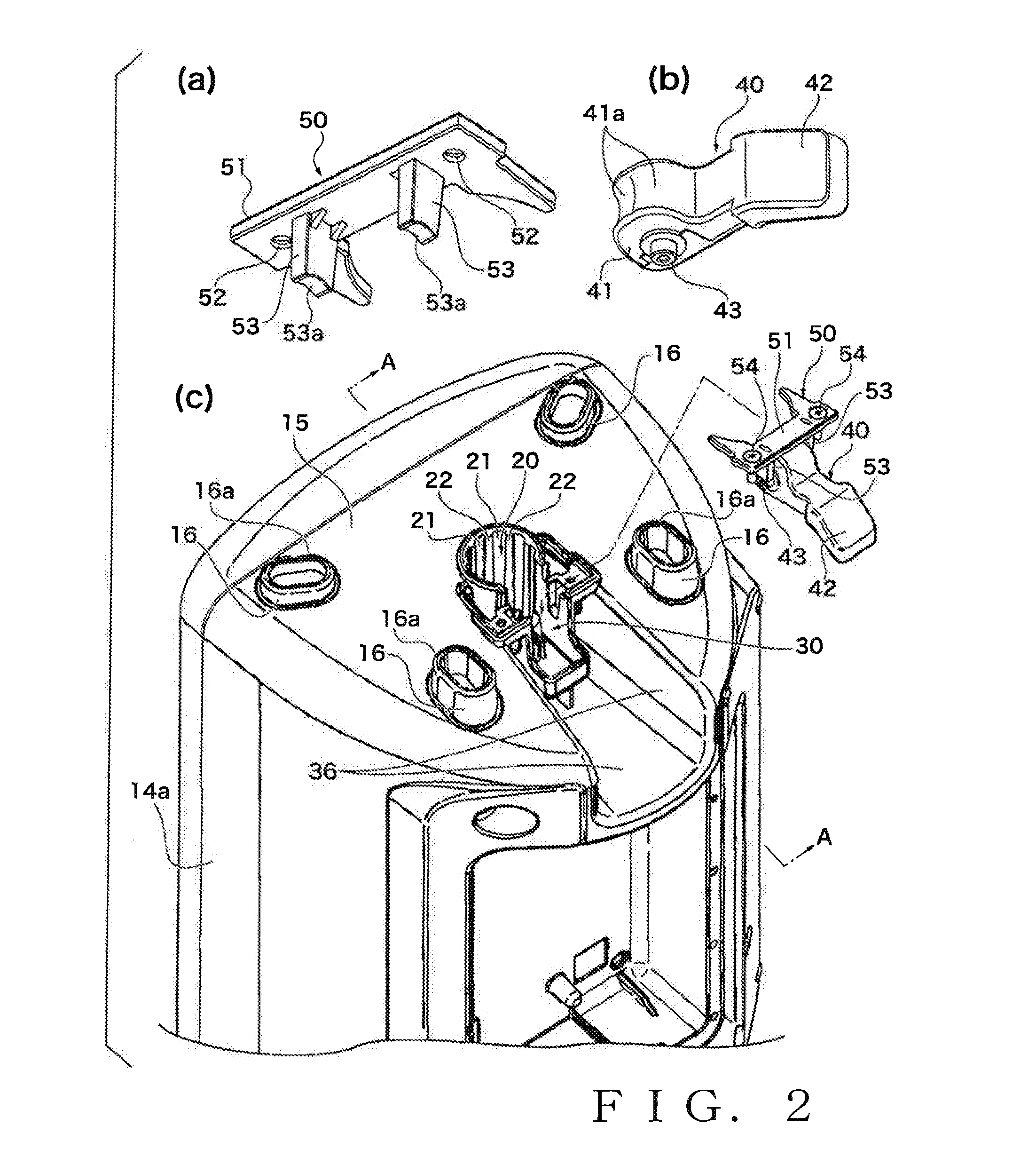
A distal end of an inserted pole makes contact with a bottom surface or tapering surface of a portion corresponding to a bottom of an insertion hole. A lever rotates about a pivot shaft, and a pressing surface facing from a recessed portion formed in the insertion hole presses a side surface portion of the pole. The pole pressed by the pressing surface is mainly received by ridge portions, particularly the ridge portions positioned on the opposite side with a central axis therebetween in relation to the pressing surface. The ridge portions are positioned on both sides of the pole with the cross section along the line A-A therebetween as viewed in the axial direction. As the lever is rotatably operated in the tightening direction, the pressing position gradually approaches the central axis, thereby increasing the pressing force.

Description

TECHNICAL FIELD[0001]The present invention relates to acoustic equipment or audio devices, such as a speaker, which can be fixedly mounted on the stand by being detachably attached to a pole of a stand.BACKGROUND ART[0002]Heretofore, there have been known acoustic equipment or audio devices, such as speakers and mixer apparatus, which are fixed to a pole of a stand. According to the disclosure of Patent Literature 1, for example, a bracket section is provided at the distal end of a stand's pole of a circular columnar shape, two bracket screws provided on a seat of the bracket section are screwed to an audio device, and the bracket section is fixed to the distal end of the pole by means of a wing screw.PRIOR ART LITERATURE[0003]Patent Literature 1: Japanese Patent No. 4496904[0004]However, with a mounting structure disclosed in Patent Literature 1, it is necessary to first fix the bracket section to the stand's pole, and, additionally, a problem of poor operability would be encounter...

Claims


Application Information

Patent Timeline
IPC IPC(8): H04R1/02
CPCH04R1/02H04R1/026H04R3/00H04R5/04
Inventor SAKURAI, YUUJIWATANABE, TSUTOMU
Owner YAMAHA CORP
Learn More