Image Processing Techniques

a graphic processing and image technology, applied in the field of graphic processing, can solve the problems of affecting the performance of the rasterization system, unable to reuse the memory of an already processed bin for subsequent binning, and large memory used to hold vertices to be processed

Inactive Publication Date: 2015-05-28
INTEL CORP
View PDF3 Cites 29 Cited by
  • Summary
  • Abstract
  • Description
  • Claims
  • Application Information

AI Technical Summary

Problems solved by technology

The memory used to hold vertices to be processed may be very large and this may in turn hinder performance of the rasterization system.
In addition, there is no possibility to reuse the memory from an already processed bin for subsequent binning because all bins already contain their vertex-shaded contents, i.e., all vertices must be processed before rasterization can be done.

Method used


Image

  • Image Processing Techniques
  • Image Processing Techniques
  • Image Processing Techniques

Examples


Embodiment Construction

[0012]Reference throughout this specification to “one embodiment” or “an embodiment” means that a particular feature, structure, or characteristic described in connection with the embodiment is included in at least one embodiment of the present invention. Thus, the appearances of the phrase “in one embodiment” or “an embodiment” in various places throughout this specification are not necessarily all referring to the same embodiment. Furthermore, the particular features, structures, or characteristics may be combined in one or more embodiments.

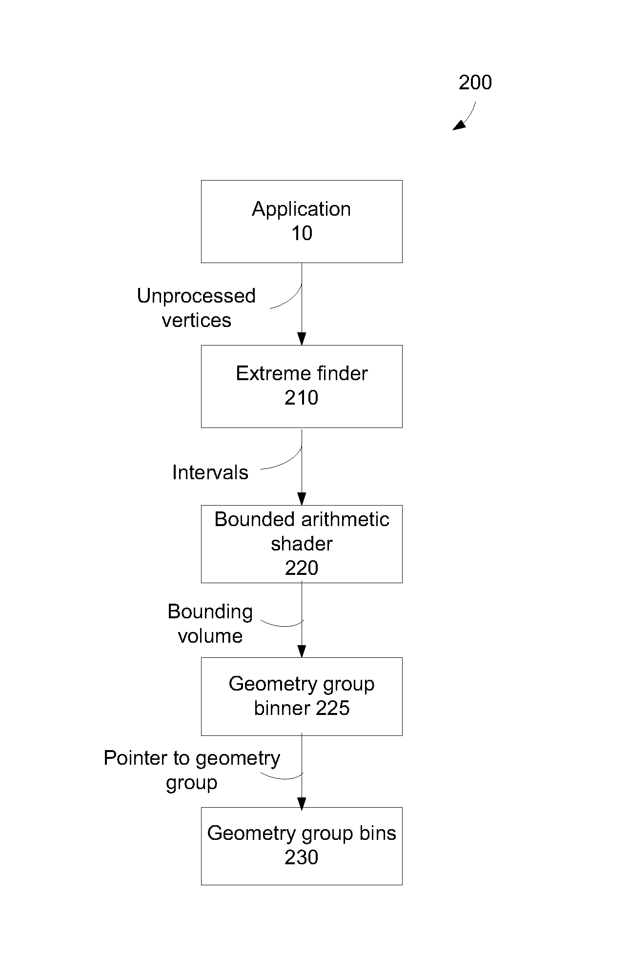
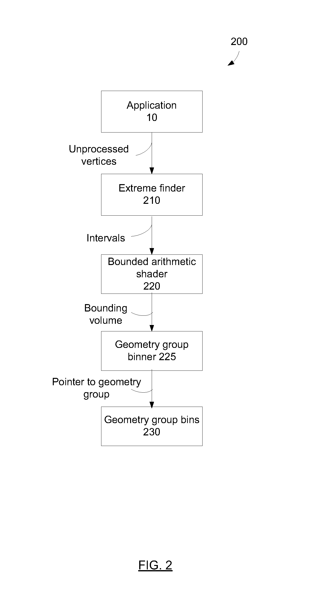
[0013]The publication in Anthony Apodaca and Larry Gritz, Advanced Renderman, Morgan Kauffman Publishers (2000) (hereafter “Renderman”) describes generating micropolygons, generating bounding volumes based on the generated micropolygons, and storing the bounding volumes and pointers to surfaces to be tessellated. RenderMan also allows the user to set a maxDisplacement parameter per geometric object, and this together with the non-displaced geom...


PUM


Abstract

Techniques are described that can delay or even prevent use of memory to store triangles associated with tiles as well as processing resources associated with vertex shading and binning triangles. The techniques can also provide better load balancing among a set of cores, and hence provide better performance. A bounding volume is generated to represent a geometry group. Culling takes place to determine whether a geometry group is to have triangles rendered. Vertex shading and association of triangles with tiles can be performed across multiple cores in parallel. Processing resources are allocated for rasterizing tiles that have been vertex shaded and binned triangles over tiles that have yet to be vertex shaded and binned triangles. Rasterization of triangles of different tiles can be performed by multiple cores in parallel.

Description

FIELD[0001]The subject matter disclosed herein relates generally to graphics processing, including rasterizing images for display.RELATED ART[0002]Rasterization involves converting an image, described in a vector graphics format, into a raster image (pixels or dots) for output to a video display or for storage. FIG. 1 depicts an example of a prior art rasterization architecture. An application 10 provides unprocessed vertices to a shader 20. Shader 20 performs vertex shading on the vertices in the scene. Shader 20 provides processed vertices representing triangles to triangle binner 25. Triangle binner 25 sorts the triangles into the tiles that the triangles overlap with on screen. Each tile has a bin where information regarding all triangles overlapping that tile is stored. Triangle binner 25 stores triangles into triangle bins 30. Triangle bins 30 represent the bins that store triangles associated with tiles. Front-end processing includes boxes 20, 25, and 30. In box 40, each core...

Claims


Application Information

Patent Timeline
Patent Type & Authority Applications(United States)
IPC IPC(8): G06T1/20G06T11/40
CPCG06T1/20G06T2210/12G06T11/40G06T15/005
Inventor AKENINE-MOLLER, TOMAS G.TOTH, ROBERT M.HASSELGREN, JON N.MUNKBERG, CARL J.CLARBERG, FRANZ P.
Owner INTEL CORP
Why Eureka
Try Eureka